


Lord Nicoll
-
Posts
4,396 -
Joined
-
Last visited
Reputation Activity
-

 Lord Nicoll got a reaction from Zachary Begley in General Intel HEDT Xeon/i7 Discussion
sweet. Here's Erebus and Ragnarok. my two inside servers. They're pretty nice beasts.
-

 Lord Nicoll got a reaction from twocows in I can feel electricity through my PC case
What you're likely feeling is 1/2 mains voltage through from the class X (and possibly class Y, those go between live and earth) capacitor that ties the 0v DC ground to live mains to reduce back EMF and EMI and other issues. That suggests the earth on your PC chassis is not sufficient to bleed the roughly 60-120v AC ripple to ground. I'd suggest you double check the earthing/grounding of the case, and if needed run a dedicated wire to a earthing rod in the ground if it's that much of a concern.
-

 Lord Nicoll got a reaction from Somerandomtechyboi in Are capacitors supposed to crackle? Please help new GPU from newegg.
I've had graphics card make those noises before, usually only under extreme loads, consider trying to take a video or recording the sound so you could show us, it might be normal but I wouldn't think so.
-
 Lord Nicoll got a reaction from Boombi in Better have 4 sticks or 2 sticks of ram despite price difference ?
It's very dependant on the sticks, what topograpgy the motherboard is, if you're manually overclocking, how many ranks are being interleaved, and the timings and speeds. If everything is the same, same timings, ranks, channels, speeds, you will only see differences in the margin of error. It's when you start to get into different memory configs that this question becomes harder to answer, so I'll use one example in the real world I had a couple months ago.
My friend upgraded his 4x8GB 2400MHz JEDEC DDR4 with 2x16GB 3200MHz not great XMP kit, and in doing so we went from 4 dual ranked DIMMs to 2 single ranked DIMMs, and despite the increase from 2400MHz to 3200MHz, the bandwidth was basically the same. He saw no performance increase and he was on a 3900X.
Higher levels of ranks perform better for the same speed, but usually can't go as fast. If you're manually overclocking 2 DIMMs with single rank would overclock further. However you'd need to push them pretty far, probably more than a normal person overclocks.
The sad part is, it's not as easy to see from the DIMM itself what config the kit is without all the codes and model numbers so before you upgrade, take some benchmarks of the performance, upgrade and see if it got any faster. Alternatively you could look for a kit that maintains the same amount of ranks and in theory should therefore be the same, while outperforming due to speed.
I'm a fairly good overclocker and can manually tune memory timings and speeds so I usually go for 2 single rank DIMMs, but a normal person not wanting to spend loads on a super high end kit of XMP memory might get better value out of 4 dual ranked DIMMs with normal speeds and timings vs 2 single ranked DIMMs. Thats 8 ranks vs 2, not hard to see how it outperforms it.
As for motherboard, if it's a T-Top board, not too common now adays, 4 DIMMs overclocks better, if it's a daisy chain board, which most are now adays, 2 DIMMs in the outer slots of both channels will overclock better.
-
 Lord Nicoll got a reaction from BiotechBen in My mic won't work on the Xbox app (PC) but will on everything else
Did you try the voice tab in the xbox game bar, I had a similar issue and it was because the app had automatically selected the wrong input device
-
 Lord Nicoll got a reaction from WildFoxy100 in DRAM LED on Motherboard with No Display Output
As unlikely as it sounds, might be a DRAM failure during use, odd it happened out of nowhere. Did you try clearing the CMOS too? Might be worth pulling the memory modules out and testing them one at a time assuming you have more than one.
-
 Lord Nicoll got a reaction from Skiiwee29 in Overvolting an RTX 3050
Unfortunatly there isn't too much more you could get out of a GPU like this, not on ambient at least, as overvolting is only something you do now with such small lithographies on more extreme levels of cooling, from chilled liquid to liquid nitrogen, but if you'd like I can walk you though the process for volt modding the card, first though I'd want to know your level of soldering capability and what equipment you have, and that you understand you could completely fry not only the card but also the the CPU, possible the RAM and motherboard too if something truely catastrophic happens (like shorting 12v to the PCIe bus, to the CPU, which would fry the SOC on the CPU and probably send 12v to the RAM and chipset)
-
 Lord Nicoll got a reaction from Lairlair in Upgraded CPU - temps went up
Sounds normal, 11th gen ran a fair bit warmer than 10th gen really under idle even, it was a 10nm process produced on 14nm. It sounds normal to me.
-
 Lord Nicoll got a reaction from oi you in Upgraded CPU - temps went up
Sounds normal, 11th gen ran a fair bit warmer than 10th gen really under idle even, it was a 10nm process produced on 14nm. It sounds normal to me.
-
 Lord Nicoll got a reaction from MingLee420 in Upgraded CPU - temps went up
Sounds normal, 11th gen ran a fair bit warmer than 10th gen really under idle even, it was a 10nm process produced on 14nm. It sounds normal to me.
-
 Lord Nicoll got a reaction from Frizz in Upgraded CPU - temps went up
Sounds normal, 11th gen ran a fair bit warmer than 10th gen really under idle even, it was a 10nm process produced on 14nm. It sounds normal to me.
-
 Lord Nicoll got a reaction from Demonic Donut in 10980XE hits 110 degrees even on a custom loop
You're not gonna get 4.8GHz all core without a binned chip in the sub 1.25v range with reasonable temps man, and you have a single slim rad, that's no where near enough. I have an XE 360 and CE 360 cooling just a 7700K and 980 Ti, when overclocked even that gets the loop warm, a 3090 and heavily OC'd 10980XE are gonna need probably separate loops with D5's and 2 rads each if you want decent temps, or one very large loop with 3 rads. That or extreme cooling, chillers, SS units. As someone who makes chillers and SS units I wouldn't recommend them for daily.
You're options are
lower the voltage and clock speed get more radiators and see if it's coolable then delid the chip (not recommended) use vapour phase change (not recommended but an aquarium pump that won't go under the dew point might work) -
 Lord Nicoll got a reaction from Dari69 in Liquid metal on 3090 water block
Yes a high quality paste should do enough to reduce the temps, along with a lotta rad space. 2100MHz is a tall ask for any RTX 3090 unless it can already do good clocks, you might need to bin cards to get one that can do 2100MHz on even water if it does 1800-1900 currently. Whats the max stable clock you get right now at what temperature.
-
Lord Nicoll got a reaction from Dari69 in Liquid metal on 3090 water block
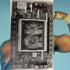
I can speak directly from experience in using LM on my watercooled Matrix Platinum GTX 980 ti (note an older card but still a hard to find card, I look forward to putting in on LN2 one day) and also using graphite pads on the memory. Yes the temps are pretty great, but quite frankly, don't, it's easy to mess up, note all the shiny areas around the package on the PCB, thats clear coat to stop shorts, and the pink nail polish on the passives around the die, it's a lotta risk for a slightly largish gain but it's not earth shattering. Look on those temps and decide for yourself. (that's idle in case it wasn't obvious, load temps are low 40's)
-
 Lord Nicoll got a reaction from IvanPicha in RX 580 4gb OC memory ?
Depends on the motherboard and CPU's IMC but I don't think 32GB of 3600 CL17 is that much, I have a 32GB kit of 4000 CL18, but it won't run on my board because my board is a bit old and was designed before A2 PCB's where around so can't really clock them well, it's also a T topology board so it prefers all 4 DIMMs to be populated but daisy chain boards will prefer only 2
-
Lord Nicoll got a reaction from IvanPicha in RX 580 4gb OC memory ?
Oh overclocking is not dangerous. Extreme overclocking is, normal gamer overclocks are fine. You're not taking soldering irons to graphics cards to hack voltage controllers and add capacitors and attaching LN2 pots to the thing, that can kill hardware, just casual overclocking won't.
-
Lord Nicoll got a reaction from IvanPicha in RX 580 4gb OC memory ?
As an extreme overclocker the first few sentences hurt me on a deep level.
Getting to the meat of the question, use GPUz to check the memory speed, it'll say. Faster memory doesn't always result in an FPS improvment but generally it can help certain situations. Each graphics card is different, some have Samsung memory, some have hynix, etc, each GPU die has different qualities of IMC, it all effects what the max stable clock speed is, saying any RX 580 4Gb can't over 2000MHz is not quite right but from what I know the 4GB ones usually have IMCs of lesser quality. It's a bit rare to see 2200MHz on the card though, that's decently high. Some models come stock with 2000MHz clocks however. What model is the card.
-
Lord Nicoll got a reaction from Somerandomtechyboi in n00b needs help - CPU/RAM Compatibility Warning
If you want it to be relevent for as long as possible wait for the new AMD CPUs to drop as the 5950X was released over a year ago. Rumours suggest probably coming in early 2022, or go with Alderlake, it's pretty alright, but I'd wait to see what the to be announced AMD stuff is like. If you think the 5950X will stay relevent the longest simply because it has more cores then that's not really the whole picture, also ultimatly DDR4 is about to be made obsolete by DDR5 too.
As for the voltage thing if you want to keep the PC for a long time it might not be the best idea to run over recommended voltages, with that said I don't think 1.45v will do that much damage.
-
Lord Nicoll got a reaction from Somerandomtechyboi in The long road to designing and building custom phase change evaporators
Oh you can use a heat exchanger instead of an SS evap head like shown there, the chillers the builds make also outperform a lot of the AC ones and aquarium chillers but they typically can't handle the same load so you gotta space benchmarks out more. You'd really wanna water a TEC, but when wateredcooled you do get some pretty low temps on it. You shouldn't need to weld or solder anything (other than maybe the TEC leads), typically we use bolts for these things
-
 Lord Nicoll got a reaction from BuckGup in The long road to designing and building custom phase change evaporators
I wasn't the one who built it into a unit so I can't say, however the person who did is a pretty well known HWBot XOCer in the extreme league, so he'd know what he's doing. Obviously our units that are built by botique builders perform much better than the ones you buy, because we build with better evaporators, larger condensers and bigger compressors and while following EPA guides we don't exactly follow the other guidelines, so units tend to use more power and maybe wouldn't be fully certified like consumer ones, however as I said, ours cool higher capacities with lower temps. One of the people on the HWBot discord, Natchfalke, built a 500 watt electronically controlled -105° 2 stage cascade cooler, now that is a mighty beast of a unit. Weights like 86KG, uses like only 1600 watts to cool 500 watts, pretty impressive.
-
Lord Nicoll got a reaction from BuckGup in The long road to designing and building custom phase change evaporators
[preface; in this post I talk about the long road of idea's and attempts at making custom evaporators for phase change coolers, talking about my rationale and why I did things the way I did, if you think you'd enjoy it why not give it a read, but at this point with all said and done the project was worth it I think. Maybe it'll inspire you or give you a good idea or two about your own projects]
So for the last few months I've been working on new evaporator designs, for use mainly in lower budget single stage units (usually called SS units but for obvious reasons I tend not to call them that, at least not around people who don't know what I mean ahahahha). By lower budget what I really mean is under €150 for everything including 3D printed mounting hardware, holds up well with SS temps, rods and nuts, springs, washers, evapator block itself. These current prototype evaporators are all 50.8mm, 2 inch round copper, C101 alloy. They use a dual flow path that is forced to crash into itself to cause more turbulance in the flow and help the pressure spike then fall again in the constrictions to ensure refrigerant is evaporated and able to absorb as much heat from the block as possible. As shown here in the first prototype to be machined (not actually the first head tested or even finished, it was left until later as the taller evap heights are harder to make) The design uses 3 concentric channels with a central chamber, On some models the refrigerant is introduced in the centre chamber and sucked out though the outer ring, these are GPU models, and on the CPU blocks the refrigerant is introduced on the outside but either can be used on either, it's mostly the suction port location that makes the centre injection design better for verticle set ups. I rate my evaporators within each diametre grouping, 50mm, 20mm-32mm, 65mm, 30mm-45mm etc. The taller the internal channels the more room there is for higher flow rates of refrigerant to expand, more surface area to absorb heat energy and the the harder and more epensive they are to make. While the surface area is most important on the bottom, the walls do help bring up heat energy to be absorbed. The shortest ones are around 20mm in height, with base thicknesses of 2.5mm to 3mm. The thinner the base the better for evaporatation however too thin and it can deform from the pressure. 3mm is the absolute thicknest it should be, with somewhere around 2.5mm being optimal while still being able to resist the pressure. The tallest evaporator in my 50.8mm family will almost certainly be 32mm tall, as at this height 3mm endmills aren't too happy about cutting that far into a pocket, to get to the desired depth the endmill will be 29mm into the part, which is almost 1:10 diametre to depth cut. At €22 per carbide 3mm end mill it's not exactly easy. The second and third evaporators I made used what I am retroactively refering to as the Gen 1 design, this design just uses straight walled channels. The Gen 2 design uses scalloped cuts in the walls of the channel for extra surface area and further disruptions to the flow paths. The first evaporator can have those scalloped cuts added to it now since It was not completed and is therefore still open. Other than plunging the endmill in partially to the wall, the process is the exact same. Most of my evaporators are TIG welded at the top, unlike most evaporators you buy that are brazed by the end user. TIG welding produces a very strong and durable weld if done correctly, which is not so easy on copper. Welding copper in general is unusualy however I learned to TIG weld on copper so I'm not that bad at it. when I start making more of these I'll likely switch to welding them in a purge chamber for as close to a flawless fusion weld as possible and ensure the copper remains impurity free.
The tools I use to make these evaporators is almost entirely my mini lathe. I use a toolpost mounted spindle with rotating endmills to cut the channels. Currently I have a really crappy "500" watt spindle with an ER11 collet. The shaft that mounts the collet to the motor is only 5mm and so has a crazy amount of deflection. This is basically unacceptable really, it's why I can only make evaps about 18mm deep currently reliable. I plan to upgrade to an ER16 spindle soon, these spindles are typically claimed to be 1500 watts and I'm included to beleive them, unlike the "500" watt one I have that I suspect is around 350 watts. The ER16 ones are inverter driven and come in both air and watercooled variets so I do suspect they're at least more of the 1500 watts they claim. The main benefit of the larger ER16 spindles is the thicker shaft really, at 5mm it can barely hold up to real cutting loads like you'd see in the channel cutting operation. My minilathe is fairly large as far as minilathes go, a 1100 watt brushed motor, 220mm x 750mm, very long for a minilathe, and about a 100mm x 100mm cross section on the bed, which is better than most of the minilathes, it works out as a 9 inch minilathe more or less, 8.7inches.
Evaporator Prototype A000, model M01(P)
Evaporator Test type A001, Model M01(T)
Evaporator Test type A002, model M01(T)
Evaporator Prototype A003, model M02(PX)
Evaporator Prototype A004, Model M03(P)
Evaporator Brazed onto a lineset
And there is it, the extent of my 6 month long expedition into designing, researching, and actually building phase change evaporators. Out of a large hunk of copper I believe was 200mm longs and cost about €100, I managed to get the raw material for 6 evaporators, and a lot of copper chips and swarf. Hopefully when I try to machine the A000 model and finish it I can get a really nice example of what these evaporators can look like when everything goes right and they come out nice. In the future I hope to electroplate them with nickel too, or as I like to call it Nicoll Plating.
[Edit] ; Wow this text editing is awful and annoying the way it has two scrolling windows inside one another, wish there was a full screen version you can enable. Sorry it's taken a like 10 minutes and 10 edits to make this post readable lol
-
 Lord Nicoll got a reaction from CommanderAlex in The long road to designing and building custom phase change evaporators
[preface; in this post I talk about the long road of idea's and attempts at making custom evaporators for phase change coolers, talking about my rationale and why I did things the way I did, if you think you'd enjoy it why not give it a read, but at this point with all said and done the project was worth it I think. Maybe it'll inspire you or give you a good idea or two about your own projects]
So for the last few months I've been working on new evaporator designs, for use mainly in lower budget single stage units (usually called SS units but for obvious reasons I tend not to call them that, at least not around people who don't know what I mean ahahahha). By lower budget what I really mean is under €150 for everything including 3D printed mounting hardware, holds up well with SS temps, rods and nuts, springs, washers, evapator block itself. These current prototype evaporators are all 50.8mm, 2 inch round copper, C101 alloy. They use a dual flow path that is forced to crash into itself to cause more turbulance in the flow and help the pressure spike then fall again in the constrictions to ensure refrigerant is evaporated and able to absorb as much heat from the block as possible. As shown here in the first prototype to be machined (not actually the first head tested or even finished, it was left until later as the taller evap heights are harder to make) The design uses 3 concentric channels with a central chamber, On some models the refrigerant is introduced in the centre chamber and sucked out though the outer ring, these are GPU models, and on the CPU blocks the refrigerant is introduced on the outside but either can be used on either, it's mostly the suction port location that makes the centre injection design better for verticle set ups. I rate my evaporators within each diametre grouping, 50mm, 20mm-32mm, 65mm, 30mm-45mm etc. The taller the internal channels the more room there is for higher flow rates of refrigerant to expand, more surface area to absorb heat energy and the the harder and more epensive they are to make. While the surface area is most important on the bottom, the walls do help bring up heat energy to be absorbed. The shortest ones are around 20mm in height, with base thicknesses of 2.5mm to 3mm. The thinner the base the better for evaporatation however too thin and it can deform from the pressure. 3mm is the absolute thicknest it should be, with somewhere around 2.5mm being optimal while still being able to resist the pressure. The tallest evaporator in my 50.8mm family will almost certainly be 32mm tall, as at this height 3mm endmills aren't too happy about cutting that far into a pocket, to get to the desired depth the endmill will be 29mm into the part, which is almost 1:10 diametre to depth cut. At €22 per carbide 3mm end mill it's not exactly easy. The second and third evaporators I made used what I am retroactively refering to as the Gen 1 design, this design just uses straight walled channels. The Gen 2 design uses scalloped cuts in the walls of the channel for extra surface area and further disruptions to the flow paths. The first evaporator can have those scalloped cuts added to it now since It was not completed and is therefore still open. Other than plunging the endmill in partially to the wall, the process is the exact same. Most of my evaporators are TIG welded at the top, unlike most evaporators you buy that are brazed by the end user. TIG welding produces a very strong and durable weld if done correctly, which is not so easy on copper. Welding copper in general is unusualy however I learned to TIG weld on copper so I'm not that bad at it. when I start making more of these I'll likely switch to welding them in a purge chamber for as close to a flawless fusion weld as possible and ensure the copper remains impurity free.
The tools I use to make these evaporators is almost entirely my mini lathe. I use a toolpost mounted spindle with rotating endmills to cut the channels. Currently I have a really crappy "500" watt spindle with an ER11 collet. The shaft that mounts the collet to the motor is only 5mm and so has a crazy amount of deflection. This is basically unacceptable really, it's why I can only make evaps about 18mm deep currently reliable. I plan to upgrade to an ER16 spindle soon, these spindles are typically claimed to be 1500 watts and I'm included to beleive them, unlike the "500" watt one I have that I suspect is around 350 watts. The ER16 ones are inverter driven and come in both air and watercooled variets so I do suspect they're at least more of the 1500 watts they claim. The main benefit of the larger ER16 spindles is the thicker shaft really, at 5mm it can barely hold up to real cutting loads like you'd see in the channel cutting operation. My minilathe is fairly large as far as minilathes go, a 1100 watt brushed motor, 220mm x 750mm, very long for a minilathe, and about a 100mm x 100mm cross section on the bed, which is better than most of the minilathes, it works out as a 9 inch minilathe more or less, 8.7inches.
Evaporator Prototype A000, model M01(P)
Evaporator Test type A001, Model M01(T)
Evaporator Test type A002, model M01(T)
Evaporator Prototype A003, model M02(PX)
Evaporator Prototype A004, Model M03(P)
Evaporator Brazed onto a lineset
And there is it, the extent of my 6 month long expedition into designing, researching, and actually building phase change evaporators. Out of a large hunk of copper I believe was 200mm longs and cost about €100, I managed to get the raw material for 6 evaporators, and a lot of copper chips and swarf. Hopefully when I try to machine the A000 model and finish it I can get a really nice example of what these evaporators can look like when everything goes right and they come out nice. In the future I hope to electroplate them with nickel too, or as I like to call it Nicoll Plating.
[Edit] ; Wow this text editing is awful and annoying the way it has two scrolling windows inside one another, wish there was a full screen version you can enable. Sorry it's taken a like 10 minutes and 10 edits to make this post readable lol
-
 Lord Nicoll got a reaction from adarw in The long road to designing and building custom phase change evaporators
[preface; in this post I talk about the long road of idea's and attempts at making custom evaporators for phase change coolers, talking about my rationale and why I did things the way I did, if you think you'd enjoy it why not give it a read, but at this point with all said and done the project was worth it I think. Maybe it'll inspire you or give you a good idea or two about your own projects]
So for the last few months I've been working on new evaporator designs, for use mainly in lower budget single stage units (usually called SS units but for obvious reasons I tend not to call them that, at least not around people who don't know what I mean ahahahha). By lower budget what I really mean is under €150 for everything including 3D printed mounting hardware, holds up well with SS temps, rods and nuts, springs, washers, evapator block itself. These current prototype evaporators are all 50.8mm, 2 inch round copper, C101 alloy. They use a dual flow path that is forced to crash into itself to cause more turbulance in the flow and help the pressure spike then fall again in the constrictions to ensure refrigerant is evaporated and able to absorb as much heat from the block as possible. As shown here in the first prototype to be machined (not actually the first head tested or even finished, it was left until later as the taller evap heights are harder to make) The design uses 3 concentric channels with a central chamber, On some models the refrigerant is introduced in the centre chamber and sucked out though the outer ring, these are GPU models, and on the CPU blocks the refrigerant is introduced on the outside but either can be used on either, it's mostly the suction port location that makes the centre injection design better for verticle set ups. I rate my evaporators within each diametre grouping, 50mm, 20mm-32mm, 65mm, 30mm-45mm etc. The taller the internal channels the more room there is for higher flow rates of refrigerant to expand, more surface area to absorb heat energy and the the harder and more epensive they are to make. While the surface area is most important on the bottom, the walls do help bring up heat energy to be absorbed. The shortest ones are around 20mm in height, with base thicknesses of 2.5mm to 3mm. The thinner the base the better for evaporatation however too thin and it can deform from the pressure. 3mm is the absolute thicknest it should be, with somewhere around 2.5mm being optimal while still being able to resist the pressure. The tallest evaporator in my 50.8mm family will almost certainly be 32mm tall, as at this height 3mm endmills aren't too happy about cutting that far into a pocket, to get to the desired depth the endmill will be 29mm into the part, which is almost 1:10 diametre to depth cut. At €22 per carbide 3mm end mill it's not exactly easy. The second and third evaporators I made used what I am retroactively refering to as the Gen 1 design, this design just uses straight walled channels. The Gen 2 design uses scalloped cuts in the walls of the channel for extra surface area and further disruptions to the flow paths. The first evaporator can have those scalloped cuts added to it now since It was not completed and is therefore still open. Other than plunging the endmill in partially to the wall, the process is the exact same. Most of my evaporators are TIG welded at the top, unlike most evaporators you buy that are brazed by the end user. TIG welding produces a very strong and durable weld if done correctly, which is not so easy on copper. Welding copper in general is unusualy however I learned to TIG weld on copper so I'm not that bad at it. when I start making more of these I'll likely switch to welding them in a purge chamber for as close to a flawless fusion weld as possible and ensure the copper remains impurity free.
The tools I use to make these evaporators is almost entirely my mini lathe. I use a toolpost mounted spindle with rotating endmills to cut the channels. Currently I have a really crappy "500" watt spindle with an ER11 collet. The shaft that mounts the collet to the motor is only 5mm and so has a crazy amount of deflection. This is basically unacceptable really, it's why I can only make evaps about 18mm deep currently reliable. I plan to upgrade to an ER16 spindle soon, these spindles are typically claimed to be 1500 watts and I'm included to beleive them, unlike the "500" watt one I have that I suspect is around 350 watts. The ER16 ones are inverter driven and come in both air and watercooled variets so I do suspect they're at least more of the 1500 watts they claim. The main benefit of the larger ER16 spindles is the thicker shaft really, at 5mm it can barely hold up to real cutting loads like you'd see in the channel cutting operation. My minilathe is fairly large as far as minilathes go, a 1100 watt brushed motor, 220mm x 750mm, very long for a minilathe, and about a 100mm x 100mm cross section on the bed, which is better than most of the minilathes, it works out as a 9 inch minilathe more or less, 8.7inches.
Evaporator Prototype A000, model M01(P)
Evaporator Test type A001, Model M01(T)
Evaporator Test type A002, model M01(T)
Evaporator Prototype A003, model M02(PX)
Evaporator Prototype A004, Model M03(P)
Evaporator Brazed onto a lineset
And there is it, the extent of my 6 month long expedition into designing, researching, and actually building phase change evaporators. Out of a large hunk of copper I believe was 200mm longs and cost about €100, I managed to get the raw material for 6 evaporators, and a lot of copper chips and swarf. Hopefully when I try to machine the A000 model and finish it I can get a really nice example of what these evaporators can look like when everything goes right and they come out nice. In the future I hope to electroplate them with nickel too, or as I like to call it Nicoll Plating.
[Edit] ; Wow this text editing is awful and annoying the way it has two scrolling windows inside one another, wish there was a full screen version you can enable. Sorry it's taken a like 10 minutes and 10 edits to make this post readable lol
-
 Lord Nicoll got a reaction from K.a.l in Gigabyte radeon R7 240 Overclocking
if you really wanna push GPU's like that, you'll need to get handy with a soldering iron and understand it probably won't last longer than a month. I killed that GT610 pushing it to the limit of what that card could do, I never even got to take it onto dry ice.
-
 Lord Nicoll got a reaction from KhaderKh in Are these normal temps?
100 watts is pretty low power usage but the overclock isn't overtly heavy. Should be more than managable on a 360mm.


