


Epitome_Inc
-
Posts
64 -
Joined
-
Last visited
Reputation Activity
-

 Epitome_Inc reacted to Hairless Monkey Boy in My 4k Monitor won't run in 4k
Try a different HDMI cable. Try Displayport.
-
Epitome_Inc reacted to 4ce_Games in My 4k Monitor won't run in 4k
The only thing I can think of is you may be using a cable that doesn't support 4k, or it is not enabled in your monitor settings
-
 Epitome_Inc reacted to Musty in Fixing an XPS with a parking ticket: Is this a terrible idea?
My boss asked me to take a look at his laptop. It was BSOD with a failure to detect hard drive message.
Our IT department looked at it twice (taking a week each time) and told him it was fine, but as soon as he turned it on it crashed again.
When I looked at it i re-seated the M.2 hard drive and it worked fine for an hour while it was sat on my desk. As soon as I moved the laptop it failed again.
I noticed the M.2 had some flex to it, and the sticky pad on top of the M.2 that I guess normally prevents it from flexing with support from the chassis was a little worse for wear.
I don't know if this is a thermal pad or not? It didn't feel or look like one I've seen before.
Anyway... i reinforced it with what I had to hand. A folded up segment of parking ticket.
Everything works now, even if I give the laptop a good shake / throw around in my bag.
I know its not a good fix, but it isn't going to cause any... long term issues is it? 😅
-
Epitome_Inc reacted to NunoLava1998 in Boot failure detected after a PC crash in the midle of a game.
Did you change anything in your BIOS settings? It sounds like it's crashing because something's misconfigured; it could be an unstable overclock, for example.
-
Epitome_Inc reacted to Kilrah in Help my pc keep killing my NVME Drive ( 4 Till now )
That's ridiculous advice, unless in very special cases or the cheapest low-endurance SSDs the endurance of an SSD will way outlast any reasonable use and the drive is more likely to fail from other causes.
An MP600 is rated for being able to have 3.6 PB written to it, good luck doing that.
-
 Epitome_Inc got a reaction from DJ46 in Antique Radio Cabinet PC Build!
Ok... things have changed a bit. My family sold our house and moved out a month ago. While clearing out the garage, we found that the radio cabinet had warped and split beyond repair. I was very upset, to say the least. But, I have a good friend (shoutout to the Dominator) who took pity on me and found a new radio cabinet that in my opinion looks even better, is in better shape, and is functional! It's a Canadian General Electric Co, model KM76. There's only minor damage to the cabinet that my buddy and I can fix pretty easily in his shop. I'm trying to find someone willing to purchase the working innards to fund some of the parts I'll need to buy for the build. If anyone knows any antique radio guys on the Canadian west coast please let me know. There's one on FB I'll be contacting today.
Once we've both had our shots I'll work on it in Dom's shop. I need all new measurements and a rethink of the layout. But I think this will look gorgeous when it's finally done.
-
Epitome_Inc reacted to DJ46 in Antique Radio Cabinet PC Build!
I believe I saw your comment under that video. I thought: "Now where have I heard about a radio cabinet build before?"
I hope the screen works out, it looks great.
Though I would consider labeling the GPU memory usage as "VRAM" because my first thought was that if the GPU is "Ded", you can usually tell without looking at a gauge
-
Epitome_Inc got a reaction from DJ46 in Antique Radio Cabinet PC Build!
I betcha thought I had given up! In the past 3 months I haven't gotten a lot done, but there is some progress. I've been working on rebuilding a 50cc scooter I bought. I've stripped the cabinet almost completely, there's just some cracks and crevices to clean out before I refinish. But the big update I wanted to share has to do with the custom hardware display I want to put into the front panel where the frequency gauges were. A HUGE shoutout to Jays2Cents for their video showing how to do this. I had almost given up on this idea, but it would seem that Aida64 Extreme has exactly what I need. I haven't sourced a proper screen yet (roughly 6" LCD w/ HDMI), and this isn't my final product. But it's a mostly done proof-of-concept. I've attached a picture of the original gauge, along with my test version that I put together in about 4 hours. I used their custom gauge option and created a gauge in Paint.net to show my GPU temp. I added the red area to show what's considered a danger zone for that card. There are 16 steps to each gauge, so I had to create 16 PNG images. It's hard to see at this scale, but the indicator needle has a bottom piece that changes angles as it goes across the gauge to give it a 3D look. I just copied it for the other gauges, but I'll adjust them as necessary for the final build. Let me know what you think.
-
 Epitome_Inc reacted to mariushm in 12v LED wiring info needed
Well, yeah, in that case each led will consume around 20mA ... so 10 leds will be 200 mA, and 100 leds will consume around 2000 mA (2A)
Won't be quite accurate because the wires themselves will have some resistance, which will be added to the resistance of those resistors, and the resistors are not exactly 470 ohm (they probably use cheap +/- 5% tolerance resistors) and the further you are from the actual power supply (long wires) the more losses are in the wires - for example, I suspect if you put 50 of those leds in a strip (all in parallel) with about 5-10 cm (2-4 inches) between them, I suspect the last leds in the chain will start to be a bit less bright due to the length of the wire adding resistance on top of the individual led resistors.
You can use those wallwarts even if they're overkill, they'll only produce as much as the leds need, so it's not like you're wasting electricity by using a higher wattage adapter.
-
Epitome_Inc reacted to mariushm in 12v LED wiring info needed
The leds themselves should have a forward voltage of 2.8v .. 3.2v and a current rating of let's say 20mA ... but i would use them at 10-15mA to give them a longer life.
If you look at them, you can see each led has a resistor hidden inside the positive wire, limiting the current and therefore protecting the led, so you can parallel as many of these orange leds as you want, each led will be limited to some amount of current based on the value of the resistor inside:
So if your leds are like this ... I'd suggest taking a very sharp blade or a knife and cutting the heatshrink (the black sleeve) over the red wire, to get access to the hidden resistor.
You can now either look at the colors on the resistor to determine the resistor value or simply use a digital multimeter in resistance mode (put the probes on the ends of resistor). Once you know the resistor value, you can figure out the voltage and the current you need.
For example, let's say that's a 470 ohm resistor. You have Ohm's law : Voltage = Current x Resistance
So: Voltage of power supply - number of leds x Forward voltage of led = Current x Resistance
Let's assume they go with 20mA or 0.02A ... Voltage - 3v = 0.02 x 470 = > Voltage = 0.02x470 + 3 = 9.4 + 3 = 12.4v which would be reasonable for their title where they say 12v input voltage
You can go the other way where you calculate how much current you'd have with various power supplies :
with 5v psu : 5v - 1 x 3v = current x 470 = > current = (5-3)/470 = 2/470 = 0.004 or 4mA which is quite low and the leds will barely light up.
with 9v psu : 9-3 = current / 470 => current= (9-3)/470 = 0.012 or 12mA which is reasonable.
You can also connect a few of them in series, if you want to use them with a higher voltage power supply, and the formula remains the same but you multiply the resistance value.
For example, if you want to make groups of 3 leds in series and each led has a 470 ohm resistor on its positive wire :
psu voltage - 3 leds x forward voltage = current x (resistance x 3 leds)
psu voltage - 3x3 = current x 3 x 470 => psu voltage = 1410 x current + 9
So for 10 mA , you'll want psu voltage = 1410 x 0.01 + 9 = 23.1v ... so a 24v power supply would be great, each led would get around 11 mA
So yeah ... if your individual leds each has one of those resistors on the wire, then you can use them like incandescent light bulbs, each led is current limited by that resistor and won't blow up.
You can find out the actual resistance value and with the formulas above you can determine how bright each led will be depending on the voltage of the power supply.
-
Epitome_Inc reacted to trag1c in 12v LED wiring info needed
If you have the part number I may be able to find it. If not you can make a somewhat educated guess with a multimeter. If you hookup your LED to power with a larger resistor around a 1K (so you don't burn anything out at all) and the put the test leads like I've shown in the schematic then you can measure with your multimeter in voltage mode the voltage drop across the LED. its not perfect because nothing about the circuit will be ideal but it can give you a good guess. You will not know how much current the LED is rated for so I would stick to 10-15mA with the absolute max being 20mA in your final design because you simply don't know what they're good for.
-
Epitome_Inc reacted to trag1c in 12v LED wiring info needed
You need current limiting on LEDs because they will burn them selves out otherwise. This can be either a current limiting power supply or a resistor. Little known fact is LEDs have a dynamic resistance which is a tangent line between a graph of forward voltage vs forward current. So as the voltage increases across the LED the current exponentially increases because the resistance decreases causing it to burn out. This is because Ohms law is I = V / R or Current = Voltage over Resistance. So by decrease the resistance while keeping the voltage the same you increase your current.
This is pictured here. The graph on the left is forward voltage vs forward current while the graph on the right shows the resistance of the LED.
So in essence the resistor will drop off any voltage thats left over after the forward voltage with the desired forward current. The formula to calculate the resistor value is derived from Ohms law. Its R = (Vs - Vf) / If
So its Resistance = voltage supply - voltage forward over forward current. To find the forward voltage and acceptable forward current of your LED you will need to look at the datasheet for the LED. Also a resistor will have to be placed in series with each LED because diodes don't always behave identically to each other. So if you had one resistor to limit the current of all the LED's one of the would have the potential of taking all the current while the others don't even light up.
Your schematic would look like this. You have a common 12V rail and then a common ground rail but each LED has its own resistor.
As an example:
So if you're LED has a forward voltage of say 3.2V and a rated current of 20mA with a supply voltage of 12V.
R = (Vs - Vf) / If = (12V - 3.2V) / 0.02A = 8.8V / 0.02A = 440Ω resistor
From here you will need to calculate the amount of power flowing through each resistor so that you can choose the correct wattage rating.
You can do that with the formula:
P = I2R or Power = Current2 x Resistance
P = 20mA2 x 440Ω = 0.176W or 176mW
Resistors commonly come in 1/8W 1/4W 1/2W 3/4W or 1W sizes. In this example we would use a 1/4W resistor because that gives us breathing room in the design.
You will need to do these 2 calculations for the leds you have. If you want to some help deciphering the datasheet let me know and I can walk you through it. Or if theres anything you would like to know more about!
-
Epitome_Inc reacted to Solarity in 12v LED wiring info needed
Just a word of warning LEDs are not current limiting. They will eat as much as they can, until the die. If you are really sure that they are rated for 12v and have current limiting resistors inside of them, then you are fine to go. The analog RGB LEDs inside of PCs that use 12v are wired with 3 LEDs in series, each color also has a resistor to limit the current. Not having a picture of link makes it hard to help.
-
Epitome_Inc reacted to mariushm in 12v LED wiring info needed
We need to know the kind of 12v led you're going to use.
By default, a basic LED does not have any current limiting mechanism, so if you just connect a led like you would connect an incandescent light bulb, the led will suck so much current it will damage itself.
Some LED bulbs with sockets have current limiting mechanism built in, same for the led bulbs for cars which have sockets. 12v led strips will almost always arrange leds in groups of 3-4 leds and each of those groups will have current limiting mechanism in the form of a resistor.
The easiest way to limit current is by adding a resistor in series with the LED or with a series of leds.
Your led will have a default forward voltage, which you should assume to be around 2.8v...3.2v depending on the chemicals used to make the led.
Some led packages have multiple led dies inside connected in series, very common packages will have a voltage of 6v (2 led dies in series, super common in monitor and tv backlights), or 9v (3 led dies in series).
If your LEDs have a forward voltage of 3v, the easiest for you considering you plan to use a 12v power supply - is to make groups of 3 leds in series and use a resistor for each group, to limit the current going through the leds.
You can calculate the resistor value using this formula Input voltage - (number of leds x forward voltage of led ) = Current x Resistance
So if your power supply is 12v, you have 3 leds each with 3v forward voltage, and you want 20mA (0.02A) going through the leds, then :
Resistance = [ 12v - ( 3 x 3v ) ] / 0.02A = 150 ohm
The amount of energy being dissipated inside the resistor can be calculated with formula P = I2 x R = 0.02 x 0.02 x 150 = 0.06 watts , which tells you it's fine to use a standard 0.125w rated resistor to limit the current, without the resistor overheating itself.
If you have more powerful leds, like let's say 100mA each, then you'd use (12-3x3/0.1 = 30 ohm (you'd round to 27 or 33 ohm, standard values, or put 2x15 or 3x10 in series, or maybe two 68 ohm resistors in parallel, giving you 34 ohm) and the power dissipated would be 0.1 x 0.1 x 30 = 0.3 watts, which means you should use a resistor rated for 0.5w, or if you parallel two resistors to get the value, 0.25w resistors would work (the current is split across the two resistors in parallel, so each resistor will heat less.
-
 Epitome_Inc got a reaction from Windows7ge in 12v LED wiring info needed
Meh, I've got like... 50 of them and only need 6. I'll just go for it. Thanks again!
-
Epitome_Inc reacted to Hans Christian | Teri in 12v LED wiring info needed
In general, components don't draw more current than they use. LEDs draw next to nothing. You will want to wire them in parallel though, as the voltage drop in series will be pretty significant.
-
Epitome_Inc reacted to Windows7ge in 12v LED wiring info needed
Amps on a PSU like this are only given as its needed. It won't force the amps in and blow the LEDs. If the LEDs are designed to run on 12V no resistor should be required. How much they draw is miniscule. We're talking mA. You could wire about as many as you like (within reason). And if you want all of them to light up at once parallel would be better.
-
 Epitome_Inc got a reaction from mousesnob in Antique Radio Cabinet PC Build!
Quick update:
I've been super busy with work, so not alot has gotten done. But I did finish cleaning out the inside of the cabinet, glued/clamped the cabinet to fix a couple cracks, and planed and cut some wood to act as the upper and lower ends of the inner cabinet cavity. I need to strip and refinish the cabinet next, along with a half dozen electronics and programming projects as part of this.
-
Epitome_Inc got a reaction from DJ46 in Antique Radio Cabinet PC Build!
Quick update:
I've been super busy with work, so not alot has gotten done. But I did finish cleaning out the inside of the cabinet, glued/clamped the cabinet to fix a couple cracks, and planed and cut some wood to act as the upper and lower ends of the inner cabinet cavity. I need to strip and refinish the cabinet next, along with a half dozen electronics and programming projects as part of this.
-
Epitome_Inc reacted to dizmo in 3rd Party Cell Vendors on BestBuy.ca
They're a solid company. Just make sure they're including the US/NA power brick.
Do you really need a phone like that though? IIRC Public Mobile doesn't have very good plans anymore.
You can get the Note10 Plus for less on Koodo.
-
.thumb.png.2f848c6abbce9391fad745d7e6383db6.png) Epitome_Inc got a reaction from dizmo in 3rd Party Cell Vendors on BestBuy.ca
Epitome_Inc got a reaction from dizmo in 3rd Party Cell Vendors on BestBuy.ca
My data speed isn't super important to me. I'm work in IT and am on wifi most of the time. I'm quite happy at PM for now, but I'll check out the other providers every few months and see what the market's like. We're with Shaw for our home internet because I got a good deal through work connections. Now that they have mobile too, I may talk to my rep in a while and see if they can compete w/ PM.
-
 Epitome_Inc got a reaction from Badomen in Antique Radio Cabinet PC Build!
Ok, got a bunch more accomplished today. Hooray for stat holidays! I've already disassembled the electronics tray, removing all the components. Today I:
Finished removing the old solder. Some of it was really thick and required a small propane torch to get off. I'll post pics of all the parts I removed once I clean them up. Drilled out the rivets and removed a couple mounts from the tray as well in preparation for sanding and priming, which I also did (pic attached). Removed the interior veneer panels since they were both warped, and one of them caused the top joint to split (pic attached).I'll glue/clamp that back together after I've stripped it in a few weeks. Drilled out the blank pins on the bottom of the vacuum tubes to 7/32 so the 5mm orange LEDs I'm ordering will fit up in there. Hopefuly they shine through into the glass well enough. Yesterday I made life-size cardboard replicas of the motherboard and power supply for test fitting. I have also ordered the open bench to put inside the radio, and it should be here in a couple days. It has a power supply mount included so I'll see if it will work to mount the power supply to the electronics tray as I planned.
-
Epitome_Inc reacted to kkpatel87 in Antique Radio Cabinet PC Build!
Cool project and good progress so far!
I would recommend using an AIDA64 compatible panel (here is one example). There is a document on the AIDA64 site showing the compatible panels.
-
 Epitome_Inc got a reaction from The_Geek in Help New build not displaying
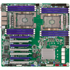
Have you tried plugging in both EATX 12v_1 and 12V_2? I see 12V_2 isn't populated.
-
Epitome_Inc reacted to Ar_Ackroyd in Help! Computer shut down out of no-where and now won't post
SOLVED. Despite both the CPU cooler and RAM lighting up, an eagle-eyed friend of mine noticed the motherboard wasn't. Although i previously tested the PSU he said he had a spare one floating around that he could lend me. Plugged in the new PSU and hoorah it booted up no problem.


.thumb.png.2f848c6abbce9391fad745d7e6383db6.png)

