Jump to content

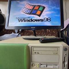
Mount psu pcb without cover. Save?

lucas_pol
Go to solution Solved by mariushm,

I would be fine with removing the SIDE walls but leave the base metal sheet on which the circuit board is screwed, and the bit with the IEC power connector.  You also want to keep the green/yellow earthing wire connected from the IEC connector to the screw of the bottom of the case (or screw that also ties down the circuit board)


Keep the LIVE (high voltage bit) as far away from components.. and it would help if you "build" a sort of wall from an insulated material (ex a sheet of aluminum covered with kapton tape or something that provides insulation, between that high voltage side and the rest of your system.


Airflow would probably be enough... but depends on you and how you control that fan speed. psus usually increase fan speeds as they produce more power and therefore more heat.

Hello! May I have a piece of advice about tinkering with psu please?

The thing is, I am working on mini itx rig, and I want it to be as compact as possible. What I want to do is remove the psu housing completely, and mount the psu pcb as is in the chassis. It is meant to be cooled via shared big fan in the chassis.

I got some questions then.


First, provided that it would be ~350W SFX PSU, will the airflow from 2x 200mm fans be sufficient in safely cooling the pcb? If you know, please tell me, what probably would be the overall heat production of psu like this?


Second thing, ground. Does PSU use its housing as the ground, or it relies on the ground provided by electrical installation? Can I safely mount it without housing?


Third thing. Is psu housing that essential in terms of electric and magnetic field isolation? In your view, is it safe to mount it 10-20 centimeters from the pc components, like cpu, ram, etc?


It is going to be the mini rig, but not very tightly-packed, and its not going to be overclocked etc. Did you guys, complete any project like this and can share some info like WIP thread or build log? I would be grateful for any info;)

Link to comment
Share on other sites

Link to post
Share on other sites

I would not tamper with the PSU since it can be dangerous I would leave the housing on for max security also opening it voids your warranty which is important on a PSU

Reminder⚠️

I'm just speaking from experience so what I say may not work 100%

Please try searching up the answer before you post here but I am always glad to help

Link to comment
Share on other sites

Link to post
Share on other sites

37 minutes ago, lucas_pol said:

a piece of advice about tinkering with psu please?

Yeah:


Don't.

The capacitors inside store enough power to kill you.

Leave them alone

NOTE: I no longer frequent this site. If you really need help, PM/DM me and my e.mail will alert me. 

Link to comment
Share on other sites

Link to post
Share on other sites

I would be fine with removing the SIDE walls but leave the base metal sheet on which the circuit board is screwed, and the bit with the IEC power connector.  You also want to keep the green/yellow earthing wire connected from the IEC connector to the screw of the bottom of the case (or screw that also ties down the circuit board)


Keep the LIVE (high voltage bit) as far away from components.. and it would help if you "build" a sort of wall from an insulated material (ex a sheet of aluminum covered with kapton tape or something that provides insulation, between that high voltage side and the rest of your system.


Airflow would probably be enough... but depends on you and how you control that fan speed. psus usually increase fan speeds as they produce more power and therefore more heat.

Link to comment
Share on other sites

Link to post
Share on other sites

Thanks for helpful tip. This will be perfectly acceptable solution, since my main goal is to reduce the noise. I’ll investigate the psu, where the ground is attached, and try to expose the psu to the airflow as well as i can.


I think i can even 3dprint the heavily perforated cover to force the airflow through the psu, securing it with insulating plastic that is already in the psu.

Link to comment
Share on other sites

Link to post
Share on other sites

Make sure you use a program like SolidWorks Flow Simulation to ensure the airflow through the PSU components is enough.  At full load you're going to want a velocity of 1.5m/s or better to ensure T1 and the BD don't exceed 100°C.  Also, keep in mind that the SR may be on the opposite side of the primary, so if you're not using static pressure in an enclosed area, you might want to beef up the heatsink on those MOSFETs so they don't exceed 110°C.  Beyond that, you'll experience thermal runaway if the PSU's OTP doesn't catch it (which it may not if it uses the fan controller for OTP instead of a supervisor IC) and the impending explosion will kill most of your components.

Link to comment
Share on other sites

Link to post
Share on other sites

Thanks. I’ll try from the other side. The psu I use now (thats much more powerfull bequiet unit) uses 12cm fan that spins around 800rpm. Whats more, the airflow is generated top-down, and the escape path of the warm air is at the back of the chassis, so the air loses most of the velocity after blasting the down side of chassis. The resulting airflow is for sure far smaller than I plan to do in itx, since the plan involves using 2 200mm fans with same rpm. Whats more i plan to mount it directly behind the front cooler at the top, so static pressure will be very high there.


One thing came to my mind with this discussion. Correct me if I am wrong, but if I would use the psu that generates much more power than I need (400-500W) this will decrease the load significantly. From the calculation I made before, it turns out that i need about 180w effective power. Would it decrease the thermal production too?


i think i’m going to just benchmark it with termometer. Since i dont plan to use any sofisticated gpu (not a gaming rig), majority of power consumption will come from cpu. I’ll run prime95 and see what will the temperatures are like.


Link to comment
Share on other sites

Link to post
Share on other sites

A power supply "generates" only as much as the components demand. 


For example, if the components need 180 watts, the power supply will take around 200 watts from the mains and "produce" 180 watts for components and the rest of 20 watts is heat, losses due to imperfect efficiency. 


Modern power supplies have their peak efficiency at around 60-70% and the gradually efficiency decreases, but not by a significant amount. 

They're also quite efficient even at low power draws, but still a high wattage power supply will tend to be less efficient at low output compared to a smaller wattage power supply.


Techpowerup usually has nice graphics for conversion efficiency, so let's take just for kicks a bronze efficiency one and a gold efficiency power supply they recently reviewed


400w Kolink Bronze : https://www.techpowerup.com/review/kolink-classic-power-400-w/

850w Corsair RMx gold : https://www.techpowerup.com/review/corsair-rmx-series-850-w-2021/


And here's efficiency 

400w: https://www.techpowerup.com/review/kolink-classic-power-400-w/5.html

850w : https://www.techpowerup.com/review/corsair-rmx-series-850-w-2021/5.html


image.png.850dbc33843e69df2fc8fc960f400a2e.png


image.png.6c31e6f52428496755004cfc2d7598e6.png


And here's some numebers:

As you can see at  around 90-100w, the bronze efficiency psu may actually be a bit more efficient .. you have The Corsair on the left producing 11w of heat to make 85w, and on the other side you have the Koling make 14w of heat to make 105 watt, so a bit more efficient. 

BUT, you could argue that the Corsair PSU will have better heatsinks and better components, capable of running at passively without any fan running, while the Kolink may be designed to rely on air flow to keep reasonably cool even at this low power output. 


At 2-300w of output power you start to see the gold efficiency in effect...nearly 93% vs 88.5% efficiency.


image.png.172f17e17ba70e6474eb2180e1bc189e.png

Link to comment
Share on other sites

Link to post
Share on other sites

3 hours ago, mariushm said:

You have The Corsair on the left producing 11w of heat to make 85w, and on the other side you have the Koling make 14w of heat to make 105 watt, so a bit more efficient. 

How? It isn't a fair comparison, honestly. 85W is lower than 105W, so it is obvious that the efficiency is less on the Corsair. I think if you compare it side by side at exactly 105W, then the Corsair will be more efficient. I've actually never seen Bronze PSUs that are more efficient at ~100W than a good, larger, gold/platinum counterpart.

Link to comment
Share on other sites

Link to post
Share on other sites

2 hours ago, boghubodaghi said:

How? It isn't a fair comparison, honestly. 85W is lower than 105W, so it is obvious that the efficiency is less on the Corsair. I think if you compare it side by side at exactly 105W, then the Corsair will be more efficient. I've actually never seen Bronze PSUs that are more efficient at ~100W than a good, larger, gold/platinum counterpart.

You can extrapolate the efficiency at any watts value ... just simplify and assume it's a line instead of a slight curve

84.958w is 88.22%

170.03w is 91.89%


You can rewrite it as


85w ... 0

170w ... 3.67


so for a 85w increase, you're looking at a 3.67% increase... you can represent it by a picture 850px wide, 37 pixels tall  or if you multiply by 50 you're looking at 4250 x 183.5px picture:


graph.thumb.png.4bb058844233b4c51fb659f42ef72f78.png

so now all you have to do is follow the line with your mouse... every 50 pixels on x axis is 1w, and on the y axis, every pixel is almost 0.02% increase (3.67% is 183.5 pixels,  so 3.67/183.5 = 0.02)

So let's see ... you want efficiency at 105w ... that's 20w above the 85w threshold, so I have to look at the 1000th vertical line from the left.... i get 141 pixels from the top, so 184-141 = 43 pixels.... which makes for a efficiency increase of 43 x 0.02 = 0.86%

So at 105w, the Corsair psu would be approximately  88.22 + 0.86 = 89.08% efficient


Now you can compare with the Kolink value that's 88.70% ....so how about that... looks like I was wrong and the Corsair psu would indeed be a bit more efficient at 105w.


Link to comment
Share on other sites

Link to post
Share on other sites

Thanks guys, this is very, very informative. I suspect that assumption that all power loss is converted to heat is preety much close to the truth, and 10-20 watts is not very much to cool.

simple maths suggest that with 200w power consumption either 300w and 400w bronze will emmit about 30w of heat, and it shall be easily cooled by planned setup. Maybe, in case of problems replacing the radiators to bigger and more copperish may help.

Based on your info, it seems that making a passive sfx psu is a reasonsble project, and assuming that i cool the cpu well, the rig will be hopefully very very quiet;)

Link to comment
Share on other sites

Link to post
Share on other sites

Create an account or sign in to comment

You need to be a member in order to leave a comment

Create an account

Sign up for a new account in our community. It's easy!

Register a new account

Sign in

Already have an account? Sign in here.

Sign In Now

×