
How can I use the second line on my character LCD?
The 8bit and 4 bit refer to how your microcontroller communicates with the LCD display.
The LCD display can use either 4 wires or 8 wires to receive the data from your microcontroller, plus 2..3 wires for non-data stuff.
See page 4 from the datasheet I linked above, I link again here: http://www.newhavendisplay.com/specs/NHD-0216K1Z-FL-YBW.pdf
See also page 9 of the controller datasheet: http://www.newhavendisplay.com/app_notes/ST7066U.pdf
And also page 23 from same datasheet
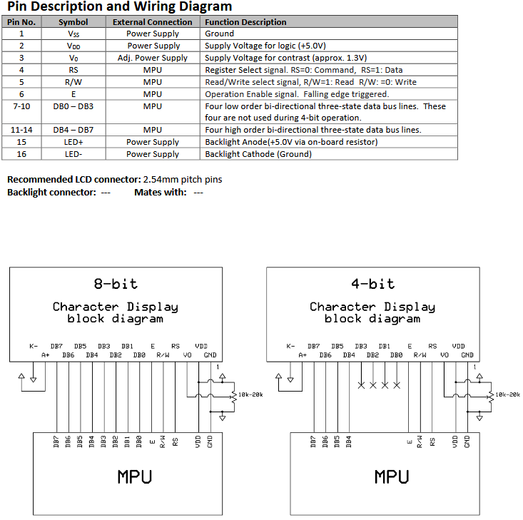
So you can use either 4 wires or 8 wires to send data to the LCD display. If you use 4 wires, then you have to send first 4 bits from a byte, then send the next 4 bits from the send byte. So it takes twice as much time to send each byte of information to the lcd display, but you use less wires.
The E wire is used to tell the lcd display that you put new data on the wires, so you basically put the bits on the wires, set the E wire to 1 (5v), wait a very short time, then set it back to 0 (no voltage. That pulse tells the lcd display that new data is on its input and he should read that and so something with it.
The RS wire is used to put the LCD display between two modes. For any command (go to home, clear display, enable cursor, etc) the RS is 0 (no voltage), and for any stuff with data (move cursor to offset, write data to position) the RS must be 1 (5v)
The R/W wire is optional, by default the lcd display is on write mode, and can be used completely in write mode all the time. If you want to use some functions, you need to set that to 5v to switch the LCD display in read mode (for example, read if the lcd display is busy, still doing the previous command, or to read what's written in the memory, the predefined font)
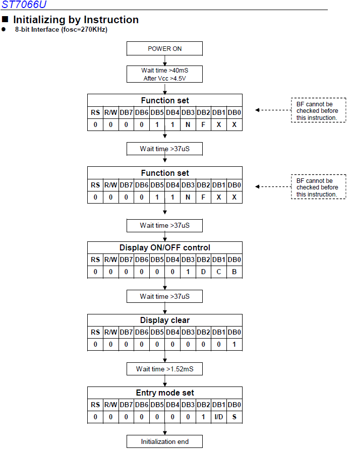
The same datasheet tells you at page 10 and page 11 how to initialize the LCD display, here's me pasting the 8bit mode from there:
// 8-bit Initialization:
// D_I = RS pin
// R_W = RW pin
// E   = Enable pin
// P1  = Port 1 of the microcontroller (8 bit, 8 wires)
// Delay = in ms, whatever in your programming language,
// may have to set oscillator frequency as a constant to
// get delay to work, depending on compiler. Read manual.
//
void command(char i) {

P1 = i;                       //put data on output Port
D_I =0;                       //D/I=LOW : send instruction
R_W =0;                       //R/W=LOW : Write
E  = 1;
Delay(1);                     //enable pulse width  >= 300ns
E  = 0;                     //Clock enable: falling edge
}

void write(char i) {

P1 = i;                       //put data on output Port
D_I =1;                       //D/I=HIGH: send data
R_W =0;                       //R/W=LOW : Write
E  = 1;
Delay(1);                     //enable pulse width  >= 300ns
E  = 0;                       //Clock enable: falling edge
}

/**********************************************************/ void init()

{

E = 0;
Delay(100);                   //Wait >40 msec after power is applied
command(0x30);                //command 0x30 = Wake up
Delay(30);                    //must wait 5ms, busy flag not available
command(0x30);                //command 0x30 = Wake up #2
Delay(10);                    //must wait 160us, busy flag not available
command(0x30);                //command 0x30 = Wake up #3
Delay(10);                    //must wait 160us, busy flag not available
command(0x38);                //Function set: 8-bit/2-line
command(0x10);                //Set cursor
command(0x0c);                //Display ON; Cursor ON
command(0x06);                //Entry mode set
}
This matches the datasheet , more or less :
once the display is initialized, you can position yourself to any location with the "set ddram address"
ex. move cursor/position to the 2nd character on the first line so offset 1, as we start from 0...
You have the instruction :

Notice that bit 7 is set to 1 ... so you would say this:
command(128 + 1); // 128 is 0b 1000 0000 which sets bit 7 to 1, and you add 1 to it which sets bit 0 to 1, and you get 1000 0001
So in the example above where the 2nd line starts at offset 0x40, you would say command(128 + 64 + offset on 2nd row) to move cursor to first character on 2nd line.

-
Topics
-

Seosamh_101 ·
Posted in Windows0 -
 1
1 -
 0
0 -
 3
3 -
 0
0 -
 1
1 -
 1
1 -
 2
2 -
 3
3 -

ShayOh ·
Posted in Troubleshooting2
-
-
play_circle_filled

Latest From Linus Tech Tips:
I Will NOT Give You $250 for Your Broken Game - WAN Show April 26, 2024
-
play_circle_filled

Latest From ShortCircuit:
I tried 20 influencer foods, here are the best… and the worst…


Create an account or sign in to comment
You need to be a member in order to leave a comment
Create an account
Sign up for a new account in our community. It's easy!
Register a new accountSign in
Already have an account? Sign in here.
Sign In Now