
[Official] Mainboard Beep and Post Codes - OEM included

This is a General comprehensive list to help the Linus TechTip Community diagnose their PC issues with simple beep codes.
These codes cover modern and Legacy hardware based on the Bios type being used per manufacturer.
Please scroll here. --->
MSI X570 LED Code reference table.


Asus Q-Code LEDs Table Reference Z690 ROG
Asus Q-Code LEDs Table Reference x399 (AMD) Chipset
5A Internal Cpu error
5B Reset PPI is not available
5C-5F Reserved for future AMI error codes
E0 S3 Resume is started (S3 Resume PPI is called by the DXE IPL)
E1 S3 Boot Script execution
E2 Video repost
E3 OS S3 wake vector call
E4 - E7 Reserved for future AMI progress codes
E8 S3 Resume failed
E9 S3 Resume PPI not found
EA S3 Resome Boot script error
EB S3 OS Wake error
EC-EF Reserved for future AMI error codes
F0 Recovery condition triggered by firmware (auto recovery)
F1 Recovery condition triggered by user (forced recovery)
F2 Recovery process started
F3 Recovery firmware image is found
F4 Recovery firmware image is loaded
F5-F7 Reserved for future AMI progress codes
F8 Recovery PPI is not available
F9 Recovery capsule is not found
FA Invalid recovery capsule
FB-FF Reserved for future AMI error codes
60 DXE core is started
61 NVRAM initialization
62 Installation of the PCH Runtime Services
63-67 CPU DXE initialization is started
68 PCI Host bridge initialization
69 System Agent DXE initialization is started
6A System Agent DXE SMM initialization is started
6B-6F System Agent DXE initialization (system agent module specific.)
70 PCH DXE initialization is started
71 PCH DXE SMM initialization is started
72 PCH deviced initialization
73-77 PCH DXE initialization (PCH module specific)
78 ACPI module initialization
79 CSM initialization
7A-7F Reserved for future AMI DXE codes
90 Boot device Selection (BDS) phase is started
91 Driver connecting is started
92 PCI Bus initialization is started
93 PCI Bus Hot Plug Controller initialization
94 PCI Bus Enumeration
95 PCI Bus Resqeust Resources
96 PCI Bus Assign recources
97 Console Output devices connect
98 Console Input devices connect
99 Super I/O initialization
9A USB initialization is started
9B USB reset
9C USB Detect
9D USB Enable
9E-9F Reserved for future AMI codes
A0 IDE initialization is started
A1 IDE reset
A2 IDE Detect
A3 IDE Enable
A4 SCSI initialization is started
A5 SCSI Reset
A6 SCSI Detect
A7 SCSI Enable
A8 Setup Verifying Password
A9 Start of Setup
AA Reserved for ASL (See ASL status Codes below)
AB Setup Input Wait
AC Reserved for ASL (See ASL status Codes below)
AD Ready to Boot event
AE Legacy Boot Event
AF Exit Boot Services Event
B0 Runtime set Virtual Address MAP begin
B1 Runtime set Virtual Address MAP End
B2 Legacy Option ROM initialization
B3 System Reset
B4 USB Hot Plug
B6 Clean-Up of NVRAM
B7 Configuration Reset (reset of NVRAM settings)
B8-Bf Reserved for Future AMI codes
D0 CPU initialization error
D1 System Agent initialization error
D2 PCH initialization error
D3 Some architectural Protocols are not available
D4 PCI resource allocation error. Out of resources
D5 No space for legacy option Rom
D6 No console output devices found
D7 No Console Input devices found
D8 Invalid Password
D9 Error loading Boot Option ROM (Loadimage returned error)
DA Boot option is failed (startinage returned error)
DB Flash update is failed
DC Reset protocol is not available
B5 PCI bus hot plug
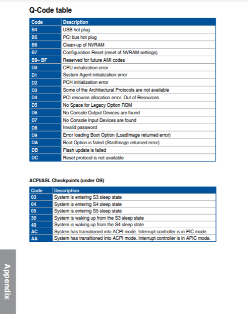
ACPI/ASL Check Points
0x01 System is entering S1 sleep state
0x02 System is entering S2 sleep state
0x03 System is entering S3 sleep state
0x04 System is entering S4 sleep state
0x05 System is entering S5 sleep state
0x10 System is waking from S1 sleep state
0x20 System is waking from S2 sleep state
0x30 System is waking from S3 sleep state
0x40 System is waking from S4 sleep state
0xAC System has transistioned into ACPI mode. Interrupt controller is in PIC mode.
0xAA System has transistioned into ACPI mode. Interrupt controller is in APIC mode.
[Motherboard] General Qcode / Q-code / Post Code table for ASUS motherboards (X299 chipset)
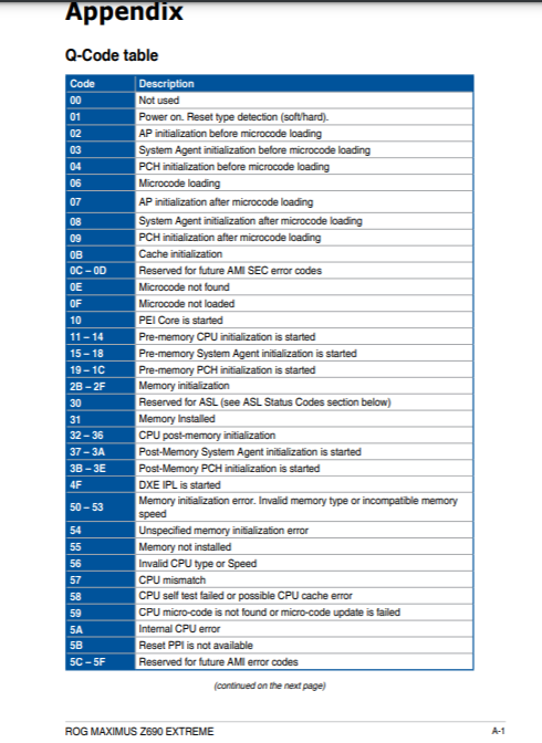
00 Not used
01 Power on. Reset type detection (soft/hard).
02 AP initialization before microcode loading.
03 System Agent initialization before microcode loading.
04 PCH initialization before microcode loading.
06 Microcode loading.
07 AP initialization after microcode loading.
08 System Agent initialization after microcode loading.
09 PCH initialization after microcode loading.
0A Initialization after microcode loading.
0B Cache initialization.
0C-0D Reserved for future AMI SEC error codes.
0E Microcode not found.
0F Microcode not loaded.
10 PEI Core is started
11-14 Pre-memory CPU initialization is started
15-18 Pre-memory System Agent initialization is started
19-1C Pre-memory PCH initialization is started
2B-2F Memory initialization
30 Reserved for ASL
31 Memory installed
32-36 CPU post-memory initialization
37-3A Post-Memory System Agent initialization is started
3B-3E Post-Memory PCH initialization is started
4F DXE IPL is started
50-53 Memory initialization error. Invalid memory type or incompatible memory sped
54 Unspecified memory initialization error
55 Memory not installed
56 Invalid CPU type or Speed
57 CPU mismatch
58 CPU self test failed or possible CU cache error
59 CPU micro-code is not found or micro-code update is failed
5A Internal CPU error
5B Reset PPI is not available
5C-5F Reserved for future AMI error codes.
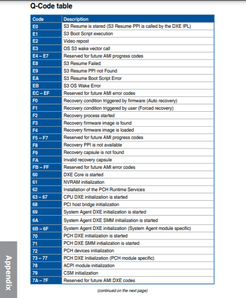
E0 S3 Resume is started (S3 Resume PPI is called by the DUX IPL)
E1 S3 Boot Scrip execution
E2 Video repost
E3 OS S3 wake vector call
E4-E7 Reserved for future AMI progress codes
E8 S3 Resume Failed
E9 S3 Resume PPI not Found
EA S3 Resume Boot Script Error
EB S3 OS Wake Error
EC-EF Reserved for future AMI error codes.
F0 Recovery condition triggered by firmware (Auto recovery)
F1 Recovery condition triggered by user (Forced recovery)
F2 Recovery process started
F3 Recovery firmware image is found
F4 Recovery firmware image is loaded
F5-F7 Reserved for future AMI progress codes
F8 Recovery PPI is not available
F9 Recovery capsule is not found
FA Invalid recovery capsule
FB-FF Reserved for future AMI error codes.
60 DXE Core is started
61 NVRAM initialization
62 Installation of the PCH Runtime Services
63-67 CPU DXE initialization is started
68 PCI host bridge initialization
69 System Agent DXE initialization is started
6A System Agent DXE SMM initialization is started
6B-6F System Agent DXE initialization (System Agent module specific)
70 PCH DXE initialization is started
71 PCH DXE SMM initialization is started
72 PCH devices initialization
73-77 PCH DXE initialization (PCH module specific)
78 ACPI module initialization
79 CSM initialization
7A-7F Reserved for future AMI DXE codes
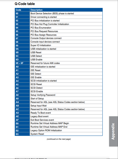
90 Boot Device Selection (BDS) phase is started
91 Driver connecting is started
92 PCI Bus initialization is started
93 PCI Bus Hot Plug Controller Initialization
94 PCI Bus Enumeration
95 PCI Bus Request Resources
96 PCI Bus Assign Resources
97 Console Output devices connect
98 Console input devices connect
99 Super IO Initialization
9A USB initialization is started
9B USB Reset
9C USB Detect
9D USB Enable
9E-9F Reserved for future AMI codes
A0 IDE initialization is started
A1 IDE Reset
A2 IDE Detect
A3 IDE Enable
A4 SCSI initialization is started
A5 SCSI Reset
A6 SCSI Detect
A7 SCSI Enable
A8 Setup Verifying Password
A9 Start of Setup
AA Reserved for ASL
AB Setup Input Wait
AC Reserved for ASL
AD Ready to Boot event
AE Legacy Boot event
AF Exit Boot Services event
B0 Runtime Set Virtual Address MAP Begin
B1 Runtime Set Virtual Address MAP End
B2 Legacy Option ROM Initialization
B3 System Reset
B4 USB hot plug
B5 PCI Bus Hot Plug
B6 Clean-up of NVRAM
B7 Configuration Reset(reset of NVRAM settings)
B8-BF Reserved for future AMI codes
D0 CPU initialization error
D1 System Agent initialization error
D2 PCH initialization error
D3 Some of the Architectural Protocols are not available
D4 PCI resource allocation error. Out of Resources
D5 No Space for Legacy Option ROM
D6 No Console Output Devices are found
D7 No Console Input Devices are found
D8 Invalid password
D9 Error loading Boot Option (LoadImage returned error)
DA Boot Device is failed (StartImage returned error)
DB Flash update is failed
DC Reset protocol is not available
AMI Bios beep codes.
1 short DRAM refresh failure The programmable interrupt timer or programmable interrupt controller has probably failed
2 short Memory parity error A memory parity error has occurred in the first 64K of RAM. The RAM IC is probably bad
3 short Base 64K memory failure A memory failure has occurred in the first 64K of RAM. The RAM IC is probably bad
4 short System timer failure The system clock/timer IC has failed or there is a memory error in the first bank of memory
5 short Processor error The system CPU has failed
6 short Gate A20 failure The keyboard controller IC has failed, which is not allowing Gate A20 to switch the processor to protected mode. Replace the keyboard controller
7 short Virtual mode processor exception error The CPU has generated an exception error because of a fault in the CPU or motherboard circuitry
8 short Display memory read/write error The system video adapter is missing or defective
9 short ROM checksum error The contents of the system BIOS ROM does not match the expected checksum value. The BIOS ROM is probably defective and should be replaced
10 short CMOS shutdown register read/write error The shutdown for the CMOS has failed
11 short Cache error The L2 cache is faulty
1 long, 2 short Failure in video system An error was encountered in the video BIOS ROM, or a horizontal retrace failure has been encountered
1 long, 3 short Memory test failure A fault has been detected in memory above 64KB
1 long, 8 short Display test failure The video adapter is either missing or defective
2 short POST Failure One of the hardware testa have failed
1 long POST has passed all tests
Award
1 long, 2 short Video adapter error Either video adapter is bad or is not seated properly. Also, check to ensure the monitor cable is connected properly.
Repeating (endless loop) Memory error Check for improperly seated or missing memory.
1 long, 3short No video card or bad video RAM Reseat or replace the video card.
High frequency beeeps while running Overheated CPU Check the CPU fan for proper operation. Check the case for proper air flow.
Repeating High/Low CPU Either the CPU is not seated properly or the CPU is damaged. May also be due to excess heat. Check the CPU fan or BIOS settings for proper fan speed.
Phoenix ISA/MCA/EISA BIOS Beep Code
1-1-2 CPU test failure The CPU is faulty. Replace the CPU
Low 1-1-2 System board select failure The motherboard is having an undetermined fault. Replace the motherboard
1-1-3 CMOS read/write error The real time clock/CMOS is faulty. Replace the CMOS if possible
Low 1-1-3 Extended CMOS RAM failure The extended portion of the CMOS RAM has failed. Replace the CMOS if possible
1-1-4 BIOS ROM checksum error The BIOS ROM has failed. Replace the BIOS or upgrade if possible
1-2-1 PIT failure The programmable interrupt timer has failed. Replace if possible
1-2-2 DMA failure The DMA controller has failed. Replace the IC if possible
1-2-3 DMA read/write failure The DMA controller has failed. Replace the IC if possible
1-3-1 RAM refresh failure The RAM refresh controller has failed
1-3-2 64KB RAM failure The test of the first 64KB RAM has failed to start
1-3-3 First 64KB RAM failure The first RAM IC has failed. Replace the IC if possible
1-3-4 First 64KB logic failure The first RAM control logic has failed
1-4-1 Address line failure The address line to the first 64KB RAM has failed
1-4-2 Parity RAM failure The first RAM IC has failed. Replace if possible
1-4-3 EISA fail-safe timer test Replace the motherboard
1-4-4 EISA NMI port 462 test Replace the motherboard
2-1-1 64KB RAM failure Bit 0; This data bit on the first RAM IC has failed. Replace the IC if possible
2-1-2 64KB RAM failure Bit 1; This data bit on the first RAM IC has failed. Replace the IC if possible
2-1-3 64KB RAM failure Bit 2; This data bit on the first RAM IC has failed. Replace the IC if possible
2-1-4 64KB RAM failure Bit 3; This data bit on the first RAM IC has failed. Replace the IC if possible
2-2-1 64KB RAM failure Bit 4; This data bit on the first RAM IC has failed. Replace the IC if possible
2-2-2 64KB RAM failure Bit 5; This data bit on the first RAM IC has failed. Replace the IC if possible
2-2-3 64KB RAM failure Bit 6; This data bit on the first RAM IC has failed. Replace the IC if possible
2-2-4 64KB RAM failure Bit 7; This data bit on the first RAM IC has failed. Replace the IC if possible
2-3-1 64KB RAM failure Bit 8; This data bit on the first RAM IC has failed. Replace the IC if possible
2-3-2 64KB RAM failure Bit 9; This data bit on the first RAM IC has failed. Replace the IC if possible
2-3-3 64KB RAM failure Bit 10; This data bit on the first RAM IC has failed. Replace the IC if possible
2-3-4 64KB RAM failure Bit 11; This data bit on the first RAM IC has failed. Replace the IC if possible
2-4-1 64KB RAM failure Bit 12; This data bit on the first RAM IC has failed. Replace the IC if possible
2-4-2 64KB RAM failure Bit 13; This data bit on the first RAM IC has failed. Replace the IC if possible
2-4-3 64KB RAM failure Bit 14; This data bit on the first RAM IC has failed. Replace the IC if possible
2-4-4 64KB RAM failure Bit 15; This data bit on the first RAM IC has failed. Replace the IC if possible
3-1-1 Slave DMA register failure The DMA controller has failed. Replace the controller if possible
3-1-2 Master DMA register failure The DMA controller had failed. Replace the controller if possible
3-1-3 Master interrupt mask register failure The interrupt controller IC has failed
3-1-4 Slave interrupt mask register failure The interrupt controller IC has failed
3-2-2 Interrupt vector error The BIOS was unable to load the interrupt vectors into memory. Replace the motherboard
3-2-3 Reserved
3-2-4 Keyboard controller failure The keyboard controller has failed. Replace the IC if possible
3-3-1 CMOS RAM power bad Replace the CMOS battery or CMOS RAM if possible
3-3-2 CMOS configuration error The CMOS configuration has failed. Restore the configuration or replace the battery if possible
3-3-3 Reserved
3-3-4 Video memory failure There is a problem with the video memory. Replace the video adapter if possible
3-4-1 Video initialization failure There is a problem with the video adapter. Reseat the adapter or replace the adapter if possible
4-2-1 Timer failure The system's timer IC has failed. Replace the IC if possible
4-2-2 Shutdown failure The CMOS has failed. Replace the CMOS IC if possible
4-2-3 Gate A20 failure The keyboard controller has failed. Replace the IC if possible
4-2-4 Unexpected interrupt in protected mode This is a CPU problem. Replace the CPU and retest
4-3-1 RAM test failure System RAM addressing circuitry is faulty. Replace the motherboard
4-3-3 Interval timer channel 2 failure The system timer IC has failed. Replace the IC if possible
4-3-4 Time of day clock failure The real time clock/CMOS has failed. Replace the CMOS if possible
4-4-1 Serial port failure A error has occurred in the serial port circuitry
4-4-2 Parallel port failure A error has occurred in the parallel port circuitry
4-4-3 Math coprocessor failure The math coprocessor has failed. If possible, replace the MPU
1-1-1-3 Verify real mode
1-1-2-1 Get CPU type
1-1-2-3 Initialize system hardware
1-1-3-1 Initialize chipset registers with initial values
1-1-3-2 Set in POST flag
1-1-3-3 Initialize CPU registers
1-1-4-1 Initialize cache to initial values
1-1-4-3 Initialize I/O
1-2-1-1 Initialize power management
1-2-1-2 Load alternative registers with initial POST values
1-2-1-3 Jump to UserPatch0
1-2-2-1 Initialize timer initialization
1-2-3-1 8254 timer initialization
1-2-3-3 8237 DMA controller initialization
1-2-4-1 Reset Programmable Interrupt Controller
1-3-1-1 Test DRAM refresh
1-3-1-3 Test 8742 Keyboard Controller
1-3-2-1 Set ES segment register to 4GB
1-3-3-1 Autosize DRAM
1-3-3-3 Clear 512K base memory
1-3-4-1 Test 512K base address lines
1-3-4-3 Test 51K base memory
1-4-1-3 Test CPU bus-clock frequency
1-4-2-1 CMOS RAM read/write failure (this commonly indicates a problem on the ISA bus such as a card not seated)
1-4-2-4 Reinitialize the chipset
1-4-3-1 Shadow system BIOS ROM
1-4-3-2 Reinitialize the cache
1-4-3-3 Autosize the cache
1-4-4-1 Configure advanced chipset registers
1-4-4-2 Load alternate registers with CMOS values
2-1-1-1 Set initial CPU speed
2-1-1-3 Initialize interrupt vectors
2-1-2-1 Initialize BIOS interrupts
2-1-2-3 Check ROM copyright notice
2-1-2-4 Initialize manager for PCI Options ROMs
2-1-3-1 Check video configuration against CMOS
2-1-3-2 Initialize PCI bus and devices
2-1-3-3 initialize all video adapters in system
2-1-4-1 Shadow video BIOS ROM
2-1-4-3 Display copyright notice
2-2-1-1 Display CPU type and speed
2-2-1-3 Test keyboard
2-2-2-1 Set key click if enabled
2-2-2-3 Enable keyboard
2-2-3-1 Test for unexpected interrupts
2-2-3-3 Display prompt "Press F2 to enter setup"
2-2-4-1 Test RAM between 512K and 640K
2-3-1-1 Test expanded memory
2-3-1-3 Test extended memory address lines
2-3-2-1 Jump to UserPatch1
2-3-2-3 Enable external and CPU caches
2-3-2-3 Configure advanced cache registers
2-3-3-1 Enable external and CPU caches
2-3-3-2 Initialize SMI handler
2-3-3-3 Display external cache size
2-3-4-1 Display shadow message
2-3-4-3 Display non-disposable segments
2-4-1-1 Display error messages
2-4-1-3 Check for configuration errors
2-4-2-1 Test real-time clock
2-4-2-3 Check for keyboard errors
2-4-4-1 Setup hardware interrupt vectors
2-4-4-3 Test coprocessor if present
3-1-1-1 Disable onboard I/O ports
3-1-1-3 Detect and install external RS232 ports
3-1-2-1 Detect and install external parallel ports
3-1-2-3 Reinitialize onboard I/O ports
3-1-3-1 Initialize BIOS Data Area
3-1-3-3 Initialize Extended BIOS Data Area
3-1-4-1 Initialize floppy controller
3-2-1-1 Initialize hard disk controller
3-2-1-2 Initialize local bus hard disk controller
3-2-1-3 Jump to UserPatch2
3-2-2-1 Disable A20 address line
3-2-2-3 Clear huge ES segment register
3-2-3-1 Search for option ROMs
3-2-3-3 Shadow option ROMs
3-2-4-1 Setup power management
3-2-4-3 Enable hardware interrupts
3-3-1-1 Set time of day
3-3-1-3 Check key lock
3-3-3-1 Erase F2 prompt
3-3-3-3 Scan for F2 keystroke
3-3-4-1 Enter SETUP
3-3-4-3 Clear in-POST flag
3-4-1-1 Check for errors
3-4-1-3 POST done - prepare to boot operating system
3-4-2-1 One beep
3-4-2-3 Check password (optional)
3-4-3-1 Clear global descriptor table
3-4-4-1 Clear parity checkers
3-4-4-3 Check virus and backup reminders
4-1-1-1 Try to boot with INT 19
4-2-1-1 Interrupt handler error
4-2-1-3 Unknown interrupt error
4-2-2-1 Pending interrupt error
4-2-2-3 Initialize option ROM error
4-2-3-1 Shutdown error
4-2-3-3 Extended Block Move
4-2-4-1 Shutdown 10 error
4-2-4-3 Keyboard Controller failure (most likely problem is with RAM or cache unless no video is present)
4-3-1-3 Initialize the chipset
4-3-1-4 Initialize refresh counter
4-3-2-1 Check for Forced Flash
4-3-2-2 BIOS ROM is OK
4-3-2-4 Do a complete RAM test
4-3-3-1 Do OEM initialization
4-3-3-2 Initialize interrupt controller
4-3-3-3 Read in bootstrap code
4-3-3-4 Initialize all vectors
4-3-4-2 Initialize the boot device
4-3-4-3 Boot code was read OK
Compaq Bios Beep Codes
1 short No error System is booting properly
1 long, 1 short BIOS ROM checksum error The contents of the BIOS ROM to not match the expected contents. If possible, reload the BIOS from the PAQ
2 short General error Unknown
1 long, 2 short Video error Check the video adapter and ensure it's seated properly. If possible, replace the video adapter
7 beeps (1 long, 1s, 1l, 1 short, pause, 1 long, 1 short, 1 short AGP video The AGP video card is faulty. Reseat the card or replace it outright. This beep pertains to Compaq Deskpro systems
1 long neverending beep Memory error. Bad RAM. Replace and test
1 short, 2 long Bad RAM Reseat RAM then retest; replace RAM if failure continues
I
BM Desktop BIOS Beep Codes:
1 short Normal POST System is booting properly
2 short Initialization error Error code is displayed
1 long, 1 short System board error
1 long, 2 short Video adapter error
1 long, 3 short EGA/VGA adapter error
3 long 3270 keyboard adapter error
Continuous Power supply error Replace the power supply
999s Power supply error Replace the power supply
No beep Power supply Replace the power supply
IBM Thinkpad BIOS Beep Codes:
Continuous beeping System board failure
One beep; Unreadable, blank or flashing LCD LCD connector problem; LCD backlight inverter failure; video adapter faulty; LCD assembly faulty; System board failure; power supply failure
One beep; Message "Unable to access boot source" Boot device failure; system board failure
One long, two short beeps System board failure; Video adapter problem; LCD assembly failure
One long, four short beeps Low battery voltage
One beep every second Low battery voltage
Two short beeps with error codes POST error message
Two short beeps System board failure
Common error codes BIOS Int 13h Function 01h
00h No error
01h Invalid command
02h Address mark not found
03h Disk write protected (floppy)
04h Request sector not found
05h Reset failed (hard disk)
06h Floppy disk removed/Disk changeline (floppy)
07h Bad parameter table (hard disk)/Initialization failed
08h DMA overrun (floppy)
09h DMA crossed 64K boundary
0Ah Bas sector flag (hard disk)
0Bh Bad track flag (hard disk)
0Ch Media type not found (floppy)
0Dh Invalid number of sectors on format (hard disk)
0Eh Control data address mark detected (hard disk)
0Fh DMA arbitration level out of range (hard error - retry failed)
10h Uncorrectable CRC or ECC data error (hard error - retry failed)
11h ECC corrected data error (soft error - retried OK ) (hard disk)
20h Controller failure
40h Seek failure
80h Disk timout (failed to respond)
AAh Drive not ready (hard disk)
BBh Undefined error (hard disk)
CCh Write fault (hard disk)
E0h Statur register error (hard disk)
FFh Sense operation failed (hard disk)
DELL INSPIRON
1 Motherboard: BIOS ROM Failure Motherboard, covers BIOS corruption or ROM error Run the Dell Diagnostics
2 Memory No Memory (RAM) detected Troubleshoot the Memory
3 Motherboard: Chipset
Chipset Error (North and South bridge error
Time-Of-Day Clock test failure
Gate A20 failure
Super I/O chip failure
Keyboard controller failure
Run the Dell Diagnostics
4 Memory Memory (RAM) Failure Troubleshoot the Memory
5 Real Time Clock Power Failure CMOS battery failure Try reseating the CMOS Battery and run the Dell Diagnostics if that does not resolve the issue
6 Video BIOS Video card/chip failure Run the Dell Diagnostics
7 Central Processing Unit (CPU) Central Processing Unit (CPU) Failure Run the Dell Diagnostics
Power LED Status Power State
Off Power is off or the system is in an S4 (hibernate) or S5 power state.
LED is blank.
Solid White The computer is in power-on state.
Solid Amber The system board cannot start initialization. There may be an issue with the system board, memory, processor or the power supply.
Blinking Amber The system board cannot start initialization or in an S3 power state. There is a power problem, a device may be malfunctioning or incorrectly installed.
DELL XPS
1 Possible motherboard failure - BIOS ROM checksum failure Run the Dell Diagnostics
2 No RAM detected
Note: If you installed or replaced the memory module, ensure that the memory module is seated properly Troubleshoot the Memory
3 Possible motherboard failure - Chipset error Run the Dell Diagnostics
4 RAM read/write failure. Troubleshoot the Memory
5 Real Time Clock (RTC) power fail Try reseating the CMOS Battery and run the Dell Diagnostics if that does not resolve the issue
6 Real Time Clock failure Run the Dell Diagnostics
7 Video card or chip failure. Run the Dell Diagnostics
8 Processor failure Run the Dell Diagnostics
DELL VOSTRO
1 BIOS ROM checksum in progress or failure. BIOS Chip System board failure, covers BIOS corruption or ROM error Run the Dell Diagnostics
2 No RAM Detected No memory detected Troubleshoot the Memory
3 Chipset Error (North and South Bridge Chipset, DMA/IMR/Timer Error for Intel platform); Chipset Error
Time-Of-Day Clock test failure.
Gate A20 failure
Super I/O chip failure.
Keyboard controller test failure.
System board Failure
(Power LED Blinking Amber) Run the Dell Diagnostics
4 RAM Read/Write failure Memory failure Troubleshoot the Memory
5 RTC Power Fail COMS battery failure Try reseating the CMOS Battery and run the Dell Diagnostics if that does not resolve the issue
6 Video BIOS Test Failure Video card failure Run the Dell Diagnostics
7 CPU Failure CPU Run the Dell Diagnostics
DELL OPTIPLEX
1-1-2 Microprocessor register failure Contact Technical Support
1-1-3 NVRAM Run the Dell Diagnostics
1-1-4 ROM BIOS checksum failure Run the Dell Diagnostics
1-2-1 Programmable interval timer Run the Dell Diagnostics
1-2-2 DMA initialization failure Run the Dell Diagnostics
1-2-3 DMA page register read/write failure Run the Dell Diagnostics
1-3-1 through 2-4-4 DIMMs not being properly identified or used Troubleshoot the memory modules and the memory slots.
3-1-1 Slave DMA register failure Run the Dell Diagnostics
3-1-2 Master DMA register failure Run the Dell Diagnostics
3-1-3 Master interrupt mask register failure Contact Technical Support
3-1-4 Slave interrupt mask register failure Contact Technical Support
3-2-2 Interrupt vector loading failure Contact Technical Support
3-2-4 Keyboard Controller test failure Run the Dell Diagnostics
3-3-1 NVRAM power loss Run the Dell Diagnostics
3-3-2 NVRAM configuration Run the Dell Diagnostics
3-3-4 Video Memory Test failure Run the Dell Diagnostics
3-4-1 Screen initialization failure Run the Dell Diagnostics
3-4-2 Screen retrace failure Run the Dell Diagnostics
3-4-3 Search for video ROM failure Run the Dell Diagnostics
4-2-1 No time tick Contact Technical Support
4-2-2 Shutdown failure Contact Technical Support
4-2-3 Gate A20 failure Contact Technical Support
4-2-4 Unexpected interrupt in protected mode Contact Technical Support
4-3-1 Memory failure above address 0FFFFh Run the Dell Diagnostics
4-3-3 Timer-chip counter 2 failure Contact Technical Support
4-3-4 Time-of-day clock stopped Contact Technical Support
4-4-1 Serial or parallel port test failure Run the Dell Diagnostics
4-4-2 Failure to decompress code to shadowed memory Run the Dell Diagnostics
4-4-3 Math coprocessor test failure Run the Dell Diagnostics
4-4-4 Cache test failure Run the Dell Diagnostics
DELL PRECISION
1-1-2 CPU register test in progress Contact Technical Support
1-1-3 CMOS read/write test in progress or failure Run the Dell Diagnostics
1-1-4 BIOS ROM checksum in progress or failure Run the Dell Diagnostics
1-2-1 Timer Test in progress or failure Run the Dell Diagnostics
1-2-2 DMA initialization in progress or failure Run the Dell Diagnostics
1-2-3 DMA page register read/write test in progress or failure Run the Dell Diagnostics
1-3-1 RAM refresh verification in progress or failure Troubleshoot the memory and memory slots.
1-3-2 1st 64K RAM test in progress or failure Troubleshoot the memory and memory slots.
1-3-3 1st 64K RAM chip or data line failure (multi bit) Troubleshoot the memory and memory slots.
1-3-4 1st 64K RAM odd/even logic failure Troubleshoot the memory and memory slots.
1-4-1 1st 64K RAM address line failure Troubleshoot the memory and memory slots.
1-4-2 1st 64K RAM parity test in progress or failure Troubleshoot the memory and memory slots.
1-4-3 Fail-safe timer test in progress Troubleshoot the memory and memory slots.
1-4-4 Software NMI port test in progress Troubleshoot the memory and memory slots.
2-1-1 1st 64K RAM chip or data line failure - bit 0 Troubleshoot the memory and memory slots.
2-1-2 1st 64K RAM chip or data line failure - bit 1 Troubleshoot the memory and memory slots.
2-1-3 1st 64K RAM chip or data line failure - bit 2 Troubleshoot the memory and memory slots.
2-1-4 1st 64K RAM chip or data line failure - bit 3 Troubleshoot the memory and memory slots.
2-2-1 1st 64K RAM chip or data line failure - bit 4 Troubleshoot the memory and memory slots.
2-2-2 1st 64K RAM chip or data line failure - bit 5 Troubleshoot the memory and memory slots.
2-2-3 1st 64K RAM chip or data line failure - bit 6 Troubleshoot the memory and memory slots.
2-2-4 1st 64K RAM chip or data line failure - bit 7 Troubleshoot the memory and memory slots.
2-3-1 1st 64K RAM chip or data line failure - bit 8 Troubleshoot the memory and memory slots.
2-3-2 1st 64K RAM chip or data line failure - bit 9 Troubleshoot the memory and memory slots.
2-3-3 1st 64K RAM chip or data line failure - bit A Troubleshoot the memory and memory slots.
2-3-4 1st 64K RAM chip or data line failure - bit B Troubleshoot the memory and memory slots.
2-4-1 1st 64K RAM chip or data line failure - bit C Troubleshoot the memory and memory slots.
2-4-2 1st 64K RAM chip or data line failure - bit D Troubleshoot the memory and memory slots.
2-4-3 1st 64K RAM chip or data line failure - bit E Troubleshoot the memory and memory slots.
2-4-4 1st 64K RAM chip or data line failure - bit F Troubleshoot the memory and memory slots.
3-1-1 Slave DMA register test in progress or failure Run the Dell Diagnostics
3-1-2 Master DMA register test in progress or failure Run the Dell Diagnostics
3-1-3 Master IMR test in progress or failure Contact Technical Support
3-1-4 Slave IMR test in progress or failure Contact Technical Support
3-2-2 Interrupt vector loading in progress Contact Technical Support
3-2-4 Keyboard controller test in progress or failure Run the Dell Diagnostics
3-3-1 CMOS power fail and checksum test in progress Run the Dell Diagnostics
3-3-2 CMOS Config info validation in progress Run the Dell Diagnostics
3-3-3 RTC/Keyboard controller not found Run the Dell Diagnostics
3-3-4 Screen memory test in progress or failure Run the Dell Diagnostics
3-4-1 Screen initialization test in progress or failure Run the Dell Diagnostics
3-4-2 Screen retrace tests test in progress or failure Run the Dell Diagnostics
3-4-3 Search for video ROM in progress Run the Dell Diagnostics
4-2-1 Timer tick interrupt test in progress or failure Contact Technical Support
4-2-2 Shutdown test in progress or failure Contact Technical Support
4-2-3 Gate A20 failure Contact Technical Support
4-2-4 Unexpected interrupt in Protected Mode Contact Technical Support
4-3-1 RAM test in progress or failure above address 0FFFFh Run the Dell Diagnostics
4-3-2 No memory in Bank 0 Run the Dell Diagnostics
4-3-3 Interval Timer Channel 2 test in progress or failure Contact Technical Support
4-3-4 Time-Of-Day Clock test in progress or failure Contact Technical Support
4-4-1 Super I/O chip failure Run the Dell Diagnostics
4-4-4 Cache test failure Run the Dell Diagnostics
Note: More recent models have eliminated the beep codes which where replaced by a single memory error pattern. Now only no memory failure conditions generate the beep code, the beep pattern is 1-3-2 (1 beep, then 3 beeps, then 2 beeps). This beep code tells you that the computer encountered a memory problem. The new beep codes emit only memory failure symptoms. Occasionally, reseating the memory modules may fix the beep code errors.
HP branded desktop or workstation PC makes beeps and does not start, a serious hardware issue is likely occurring.
The following beep codes are a reference to many HP desktop and workstation computers. Use these codes first before referring to the other code lists:
1 short beep and 1 long beep
Memory problem
2 short beeps and 1 long beep (repeats 5 times)
Unable to initialize video or video card required but not installed
3 short beeps and 1 long beep
CPU configuration error or CPU type is not compatible
The following beep codes are common to many HP and Compaq desktop computers that can occur while restoring, flashing or updating the BIOS
1 short beep
Legacy floppy drive or CD/DVD drive not detected
2 short beeps Floppy diskette or compact disc not detected
3 short beeps
Unble to start flashing (such as when missing a utility or BIOS image)
4 short beeps Flashing failed (checksum error, corrupted image, etc.)
5 short beeps BIOS recovery successful

-
Featured Topics
-
Topics
-
 0
0 -
 0
0 -

f23948 ·
Posted in Programs, Apps and Websites0 -
 0
0 -
 0
0 -
 0
0 -

Aleph256 ·
Posted in Storage Devices0 -
 15
15 -

Bonznumber1 ·
Posted in Windows0 -
 0
0
-


Create an account or sign in to comment
You need to be a member in order to leave a comment
Create an account
Sign up for a new account in our community. It's easy!
Register a new accountSign in
Already have an account? Sign in here.
Sign In Now