


WEEEEEE
-
Posts
183 -
Joined
-
Last visited
Recent Profile Visitors
1,602 profile views


.thumb.png.6a04d5ce05a353866bd438a9fcbc512b.png)

WEEEEEE's Achievements
")
-
Suggestions on cheap 120GB SDD's, preferably under $65, in order to upgrade an old laptop (thinking about doing a fresh install). Speed isn't really the biggest concern. Also, any other things I should be worried about while upgrading (like transferring drivers, ect)?
-
is two volts and one amp the same as two amps and one volt
WEEEEEE replied to AnalogCanavity's topic in Hobby Electronics
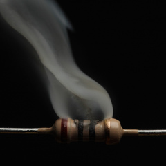
The way I see it, OP's question can be interpreted in 2 different ways, so I'll try my best to explain both: I have a fan that says it takes 2V at 1A, if I were to power this using a 1V supply capable of 2A, what speed would the fan spin at? If the fan were a resistive load, then the answer would be fairly simple. Since the fan draws 1 amp of current when powered with 2 volts, it is equivalent to a 2 ohm resistor, meaning that when powered by 1V, it will draw 0.5A, or 500 mW, as is given by the equation I=V/R, where I is current in Amps, V is voltage and R is resistance in ohms. This isn't the case however, since a fan is an inductive load, meaning that it gets more complicated. However, the basic principle remains the same. A load (fan, lightbulb, whatever) will only draw as much current as it requires, and generally as the voltage increases, it will require more current, and as it decreases, it will require less. It doesn't matter if a 1V supply is capable of giving 10A or 10000A, if the load only requires 1A, it will only draw 1A. In this case, the fan would spin slower. I have a fan that says it takes 1V at 2A, if I were to power this using a 2V supply capable of 1A, what speed would the fan spin at? The fan in this scenario would want to draw more current, but would be limited by the amount that the PSU can supply, therefore it might spin at the same speed, however powering things with more voltage than they are designed for is a generally bad idea, and your fan may end up looking like the resistor in my profile picture, so don't do this. -
Will the i3 bottleneck a rx 460?
WEEEEEE replied to VengeanceGamer's topic in CPUs, Motherboards, and Memory
Not really, they should be fine. -
Adjust RGB with sliders for RGB Led Strips
WEEEEEE replied to TheNuzziNuzz's topic in Hobby Electronics
The best way to drive LED's is by the number of amps, not the voltage. The only reason the LED gets brighter past the forward voltage is because of their internal resistance (with an ideal LED past Vf the current consumption would be infinite). I don't think we need to really worry about that for OP's use case scenario, since LED strips have onboard current limiting resistors, which regulate the current anyways. To answer OP's question, looking at the device that @W-L linked, it uses PWM control, meaning that you could replace the 3 onboard potentiometers (knobs) with slider potentiometers (aka faders). Keep in mind that the slide pots and regular pots are the exact same thing. You would do this by first desoldering the potentiometer that is already on the controller (be sure to note down which pins of the potentiometer are connected where). Then solder 3 wires to the spots where the potentiometer's pins used to be, and then connect these wires to the corresponding pins on the slide potentiometer. (see diagrams below for further clarification). Since the controller uses PWM, you don't have to worry about any other ratings other than the resistance (this should be written on the back of the potentiometers in the controller, which unfortunately means I can't recommend you a specific slide pot until you actually get the controller and open it up). If the resistance isn't on the back, then you can measure this using a multimeter (assuming you have one). In summary: Desolder the regular potentiometers, and connect slide potentiometers in their place via wires to the correct places on the board. Oh and credit to Fritzing for the images.
-
Adjust RGB with sliders for RGB Led Strips
WEEEEEE replied to TheNuzziNuzz's topic in Hobby Electronics
Actually I just remembered that I once saw these used in a DIYPerks video: http://www.ebay.com/itm/172055327012?rmvSB=true or http://a.co/fB36KuI Basically these were originally meant to control the speed of DC motors, however they can be repurposed to handle LED's as well. If you replace the onboard potentiometer (the dial), and instead hook up your faders, then that should be able to dim the LEDs. -
Adjust RGB with sliders for RGB Led Strips
WEEEEEE replied to TheNuzziNuzz's topic in Hobby Electronics
As far as the faders go, they seem to just be slide potentiometers (though for whatever reason they are way more expensive than regular slide pots). So you could just hook them up to an arduino's analogue input, and use that to control the brightness via a PWM signal that goes through a MOSFET. That being said, an arduino is totally overkill for this, so something like a 555 timer might be better... though that may be kinda difficult. OP most likely can't connect the slider pot/fader directly in series, that would probably dissipate to much heat. Sounds like some basic common anode LED strips from the description. Problem with using such a device is those tiny on board transistors don't look like they can handle 2.5A. -
Yes, it does. I recommend looking at newegg for info, amazon's product descriptions are terrible.
-
Look at the PSU tier list, pick out one from the tiers 1 and 2, with a wattage of >650W (750W is ideal).
-
Here is a rough equivalent performance wise to the PC OP listed but new: http://au.pcpartpicker.com/list/FhQvbj There are a few minor differences (the mobo isn't nearly as nice, and the PSU is of significantly lower wattage, not that it really matters without SLI), but otherwise the two builds are fairly similar.
-
750W is more than enough, actually kinda overkill in fact.
-
An H81 board can't overclock a cpu. Wait a second, looking this board's product page, MSI says it comes with OC Genie 4. I know there are some non Z-series boards that can OC, but I didn't think that this was one of them (or perhaps this is some form of "OC lite", that does not require a z chipset?). Idk, not really well versed in these things. As far as the OP's question goes, it is extremely unlikely that changing the PSU would have affected performance. You may want to try using your old PSU again if you still have it, and seeing if the performance goes back up again (try getting some actual numbers).
-
Actually a motherboard (or any other electronic component for that matter) will never draw more power than it needs, regardless of the quality of the PSU, unless the PSU decides for whatever reason that it wants to provide voltage (which will really only happen with no-name brands).
-
Well I assume by transformer you mean the whole PSU (as in the older terminology of referring to any PSU as a transformer). Otherwise as @SLAYR said, the "transformer" is a component that is soldered on to the board of the PSU. You could just get all of the wires, put them in a tube of some sort (or ziptie them together), and have all of the wires go into the case. Some non-modular PSU's sorta do this already (at least for the first few inches) since all of the wires come out of one hole. You can use extensions if the cables aren't long enough.
-
I know some people have done Raspberry Pi wall calendars that integrate with Google Calendar, maybe you could make a miniature version that only shows todays/this weeks events (though the usability of this may depend on how heavily you use google calendar)? I have also always wanted a device that draws notifications from multiple sources (email, social media, ect), and displays them on a small display. Maybe something like that could work for you as well?
-
If it does fail, than it may take another component with it. However the odds of this unit ever failing are pretty low, so you don't really have to worry, at least not with your current hardware.


