

p0Pe
-
Posts
270 -
Joined
-
Last visited
Content Type
Forums
Status Updates
Blogs
Events
Gallery
Downloads
Store Home
Everything posted by p0Pe
-
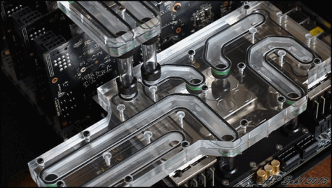
thanks man! the stickers matches the color theme so they stay:D Here they come:D Glad you like it! Here they are:D It has been a while under way, and with some complications but I am proud to finally present the HEX GEAR R80 - Rhino project! Specs: Case: HEX GEAR R80 CPU: Intel i7 5960X Graphic cards: 4 x NVIDIA GeForce GTX Titan X OS drive: Intel 750 ssd 1.2TB PCIe Secondary drive: KLEVV Urbane 480 gb ssd Motherboard: ASUS X99-E WS RAM: 64 GB KLEVV CRASS DDR4 ram PSU: Corsair AX1500i Fan controller: Aquaero 6 Watercooling: EK Water Blocks blocks, radiators, reservoir & pumps Fans: EK vardar Fittings: Bitspower Sleeving: Teleios Sleeving Tubing: E22 solid tubing This build was done to test out the thermal capacity of the R80 case, and I know that a lot of you will question why the Titan X was used this close to GTX 1080 release, and the answer is simple, I wanted to put a LOT of heat into the watercooling system to test a "worst case scenario". Also, the new cards are not using as much power, and the titan x's where available now. CPU is running at 4.4 GHz @ 1.3 Vcore GPU's are running at 1375 MHz I will let the pictures do the talking:D Since this entire build was done to show how much you can cool with the R80 case, let’s get some results on the table! Worth noting is that the fans goes all the way up to 2200 RPM, but since I do not think anyone would be satisfied with having their system running at that noise level, I decided to test what the minimum fan speed for acceptable temperatures would be. The system runs with fans at 500 RPM while Idle, so it is barely audible, but what happens when it get pushed to the max? First of all I overclocked the CPU and GPUs to their limits to get most the performance possible out of the system. Then I ran a 3D mark firestrike test, which you can see by following the link below: http://www.3dmark.com/3dm/11648520 The system did not get anywhere near hot on this test as the benchmark is somewhat short. So to get some better real world results, I decided to push the system with a few classic stress testing tools. CPU stress test – Keyshot The first test I did was with the render program Keyshot, which utilizes the CPU to the maximum, to render animations and 3D models. During this test, the system used a whopping 600W. I suspect that the reason this number is so high is because of the overclocked CPU that was fed a generous 1.3 Vcore. The picture above is the thermal setup where you are able to see all the temperatures in the testing setup. In each box is a description of what the graph shows, and in the right of each box is a number of values showing respectively: The highest value measured The lowest value measured The average value over the time measured The time shown on the graph (not to be confused with total up time – This timer only shows how far back the graph logs) Looking at the picture above you see that keyshot ran for just about 30 minutes with the CPU reaching a maximum temperature of 72 C° on the cores, and 75 C° on the package. No doubt that this temperature can be improved by lowering the Vcore, or lowering the overclock. It is worth noting that smaller chips like the 6700K would not get anyway near this hot at the same overclock. Looking at fluid temperature and fan speed, the fluid reaches a max of around 35 C°, which gives it a delta c on 11c from the ambient room temperature with the fans spinning at a max of 1200 RPM. Graphic card stress test – Furmark If we go on to the more extreme benchmark called Furmark, which will stress all grafic cards to the max, you can really see where the 1500W power supply comes in handy. At this test, the system is pulling a whopping 1400W from the socket! I did also try running both Keyshot and Furmark at the same time, but this actually led to a lower total power consumption as well as lower overall temperatures, so this was without a doubt the most stressful test for the system. The graphic cards have been overclocked to the maximum stable clock which was +200 MHz on the core, and +500MHz on the RAM. Looking at the temperatures, you see that the GPU temperatures reaches a maximum of 61 C°. The fluid temps climb up to just above 50 C°. All this with the fans spinning at a max of 1400 RPM. Turning the fans up a few hundred RPM did lower the fluid temp to just above 40 C°, but again, I where testing with lowest fan speed needed. Overall real world test – Crysis 3 Last test is what I would consider a “real world scenario” with the CPU overclocked to 4 GHz and the GPU’s with the same overclock as before. I turned the heat up in the testing area a bit, now reaching an ambient temperature of 26 C°, and then sat down playing Crysis 3 for three hours straight. I aimed for a slightly lower fluid temperature so the fans was put to a max of 1500 RPM, giving very fine temperatures on both the graphic cards and the CPU during the entire gaming session. Conclusion: The 60 mm thick 480+360 radiator in this build has proven to be more than capable of cooling this entire overclocked system. Thinking about how this system draws almost 1400W from the socket under load goes to show that if you are planning on a SLI system, you will never run into any problems cooling wise and can have your fans running at a very low setting. If you still think that you need more cooling, there is the option of upgrading the case to fit two 420 mm radiators, which would increase the total radiator surface from 100800 cm^2 to 117600 cm^2.
-
Thanks man! Bottom fans will pull air in, top fans will blow out. I already removed the sticker:D Thanks man! I think you will enjoy the final pictures as well then:D It really is the material price that is jacking up the MSRP. For example, the alu profiles is almost 4 kilo´s alone. Most other cases are sheetmetal of very thin metal, and then some injection molded plastic. Grab a snickers instead! Final pictures almost ready! Small teaser!
- 166 replies
-
- 10
-

-

-
Thanks! Haha, that guy has too many GPU's! How is that one coming along? Really looking forward to see it:D Small upgrade before the finished shots! I needed to swap out the accent packs to something more fitting to this build. Thankfully this is actually quite easy, even with a full stocked build. First, remove the 4 big M8 bolts, and the 7 small bolts. When taken off, next step is to remove the acrylic panel itself. Make sure that the PC is on its side when doing this step, and be a bit carefull when taking it off. This also opens up for some interesting shots that you normally cannot get. Still like the looks of these ram:D Quad bridge standing strong! When done, put on the new accent pack. And all done! Same steps with the front panel Last thing to do is put in the start button! Lets fill this thing up!
-
That is a loooot of fans. How much radiator capacity do you have in there?
-
I might get the one with a 5inch screen size simply because the 5.5" of the oneplus one is too big IMO.
-
Thanks! I look forward to show the final pictures and hear what you think:D I love that it is the pumps that you find overkill in this system I actually tried bent hardline, but quickly went back to this with fittings as I simply think it looks better.
-
Thanks! Tubing update! Got all tube cut to length, cleaned up the edges, and cleaned the tubes! Also put all cables in place, and booted the PC up quick to see if everything registered, and it is running smooth! All cards and cpu block installed. Really like the looks of those cards. It is a shame that EK does not make quad clear GPU bridges I am using this getto mount to cut the acrylic tubing. And this drill attachement to trim the edges. This is also handy for taking a mm or two off the tube to get it to the perfect length. Sometims accident happens and too much is taken off. It actually makes a huge difference for the final result. Started with the GPU - cpu piping and worked my way from there. It is hard to exactly plan a loop like this, so I pretty much just worked with the fittings I had, and tested different setups. I put tape on the tubes in order to not scratch them when doing the trimming with the drill. The first pump is actually located a bit over the reservoir, but this will not be an issue, as the weight of the fluid will force it into the first pump, and "jumpstart" the filling process. Done! Some of the tubes looks a bit off, but that is just because they are a bit out of place, and needs to be "pushed back". All tubes cleaned and ready to be put in again. Time to get the cables in there.. God there are so many cables! But the 180 comb really tidies it up:D Other angle. Everything in place! Just some fluid and final details to go! There is now one single open slot on the PSU. Which is just a testimony to how many cables was made for this thing:D
-

Hi, will you consider selling the aquaero scree…
p0Pe replied to Neeq's status update on p0Pe's profile
I already sold it to a buddy who was in the same situation, sorry. -
I think you have to do it yourself. But it is really easy, and the components for the mod is super common. If you know how to solder, it should not be an issue.
-
Aquabus works great if you get the aquacomputer pumps. But just make this mod, and you can controll the pumps from the aquaero easily. Just draw 12 v from the PSU, and run the PWM and RPM line into the aquaero with this mod. It is actually the pumps that does not follow the PWM standards.
-
Alright, small hickup! I found out that the PWM pumps does not work with the aquaero 6 I got because aparently the D5 pumps does not follow the PWM standard or some stuff, and does not have 5 volts on the PWM signal line so it can be registered on the aquaero. So long story short, since the pumps is not drawing 12v from the aquaero itself, but directly from the power supply, it is possible to take the 12 volt line from the aquaero, convert it to 5 volt and feed it into the PWM signal line. Before this mod, the pumps would run at a constant 60% speed aka 2200 RPM which was kinda noisy. With this mod, they can now run as low as 1100 RPM, and possibly more, making them dead silent! A big thank goes out to Darlene / IT Diva from oc.net for helping me figure out the correct resistors to use! This is now the finished mod looks like. From left to right: 1/4W – 2.2K resistor 1/2W – 1K 1W -5.1v zener diode To make it all neat and tidy I bent the resistors and diodes and put them into one of the empty pin holes of the 4 pin connector. I could have made this mod directly to the cable that went from the pumps, but since I already sleeved that, I decided to make an extender instead. Finishing it up with some heatshrink. Stealthy!
-
Haha, thanks! It is hard the first few times until you nail the technique, then it is all patience from there 10 yeah. But if you use the stock cables it is not a problem, as you can put a single GPU on a single cable. It is only because I use two full cables per GPU to make the sleeving easier. Looks like my 4 titans are in the low end But I cant really seem to get them any higher sadly.
-
That is some real impressive overclocks, and also a great looking build. I am a complete noob when it comes to overclocking, so I have no idea where to start. Currently all I have done is just ramp up the multi to 45, and then manually set the vcore to 1.375. I do not actually know what is the limiting factor, but I just found out that the ram I have is only 2133 mhz, and do honestly not know if they are bottleknecking anything? This is the build I am benching on, and I have actually found that the radiator capacity in this thing is more than able to handle the load. Regarding the graphic cards, I get bsod whenever I try and overclock them past +210 mhz core in MSI afterburner, so I am still stuck there Thanks for the picture of your overclock. I will give it a few looks.
-
Jesus that is some serious GPU and CPU overclock there! What are you cooling the CPU with? I cannot seem to get mine past 4.5 ghz, but have also not tried to run over 1.4 vcore. I also have problems getting my titan's higher than 1354 mhz Cooling should not be an issue. Benchmark: Fire Strike CPU: 5960x / 4500 MHz GPU: Nvidia GTX TITAN X 4 way SLI GPU Core: 1354 MHz GPU Memory: 1952 MHz Score: 32616 3DMark Link: http://www.3dmark.com/3dm/11648520?
-
Here you go man. I have no idea how that compares to other scores though, as I am unfamiliar with the benchmark As wished! See below:D Thanks. I think:) As stated in the reply to you, just simply subscribe to this thread. If you want to see more stuff like this, you can also give my facebook and youtube page a like/subscribe. Update time again! This time a quite big one. Or at least there went a LOT of hours into the preparations for this. As well as a LOT of cable. All in all I think I used abou 70-80 meters of cables for this thing! All in all there is a bit over 115 individually sleeved wires in this build! When I make wires for builds where I want a specific length of cables, I always start out by making the end that plugs into the components first. Then I route the cables the way I want them, and figure out what length they circa needs to be, and adds around 5 cm. I actually had to take out the 6 pin that goes into the motherboard and suply's extra power to the graphic cards because I had no room in the PSU for it Oo. Almost too bad as I quite liked how it ran over the graphic cards. But such is life. Testing showed that there was no performance or stability loss by taking this out, and no extra overclock to earn from it (when not running LN2 or other crazy voltmods, which is what I think this power plug is meant for) Closeup of how the pumps are sleeved. It works great, but it was a major pain in the bum to sleeve. Rear side with everything routed how I wanted it. Aquaero is not mounted in this picture, so I had to take that into considderation. With the first few cables finished. As you saw in the previous pictures, I start out by making all the ends in one end, and then route the cables. I then cut the other end so it fits with the PSU, and the length the cables needs to be, crimp it, and put them into the connector. And BOOM! A few hours later, the rest of the cables got connectors on the other ends as well. You have to be careful not to switch some of the wires this way as it is not super easy to see what wire is going where. But I have almost sleeved enough corsair power supply's by now to know the pin layout of the different ones in my sleep. Really like this quad comb. The thing is a beast! From the rear. Do not mind the zip ties, they are only in there to keep the different bunches of wires together for when I put connectors on them, and to keep the wires in the "route" I want them to go. All the wires out of the build for testing with a PSU tester. Proud to say that everything worked the first time around! So no magic smoke in this build! I also managed to almost completely fill out the PSU with plugs! The only ones available now is the sata/moles plugs which is kinda scary! Next up is piping!
-
Can't have that, can we now @Maki Role. I am excited to see how the graphic card will look on the backside of that distributing plate. Seeing you do that makes me sad that I never got my "flatpacked" concept realized The next 10 days are going to be fun for you. Good luck, and I look forward to the end result! You did not even need a case to be a top contender in this one.
-
Project Exometry: An Endeavour on a Functional Prototype
p0Pe replied to sigmaeleven's topic in Build Logs
Great presentation, and interesting project. Make sure that you take your time and sand and polish the edges after lasercutting as they will be very visible in this mod. Also, please find some sexy bolts and nuts, as they, again, will be so visible. I look forward to see what you come up with! -
Posts like that always turns talks about VR into low level console war threads, and does nothing good for VR adoption. If you can find a source for that claim, I will happily read it. And by source, I do not mean a vague reddit post by Palmer Luckey that can be interpreted 10 different ways.
-
If you are not willing to put time and money into making a website, you will never get an audience. The saying is "build it, and they will come", not "Wait for them to come, then build it" Regarding VR, I am just sitting here, enjoying my Vive massively. I look forward to also try out the Oculus so I can compare the two.
- 7 replies
-
- 1
-

-
- oculus rift
- htc vive
- (and 2 more)
-
Sure, I will get that ran later. Should SLI be disabled first, or does that not matter?
-
max draw at cinebench = 660W at 4.5 ghz / 1.375 vcore max draw at furmark = 1050W at 1350 mhz core clock max draw at firestrike = 1250W All measurements was taken from a watt o meter, so directly from socket, and PSU effeciency loss has not been taken into considderation. These are just the raw numbers. I will try and run cinebench and furmark together later today. This basicly covers it. I will post another update tonight with more sleeving!
-
Haha, lets hope it does not get removed So am I ! Soon! Did another run with some better clocks. I cannot seem to get anything higher sadly But a disclaimer - I am a complete noob with overclocking! http://www.3dmark.com/3dm/11648520?
-
I have no idea. I had no problems on the engineering station I will do some more troubleshooting today. Meanwhile, check out the way I routed the 24 pin cable:D
-
I am actually only running a single loop, so I can only use one color. I am glad you like it. I will send you a PM later:) Thanks! I also love the look of them myself. Make sure to make a log here as well! Haha thanks Randy! Alright guys, I quickly put all the hardware together yesterday to test out the system. But I am having a few problems that I hope is driver related. Whenever I enable SLI, I am getting "out of range" on my monitor when I boot up, or start a full screen game. Unplugging, and plugging the monitor in again solves this, but with the newest nvidia driver, every time I run something full screen the monitor just goes blank, and I have to turn the power button to get the system to shut down. I tried: Dissabling secure boot and enable CSM in bios Updated bios to newest version Testing all cards individual, all works fine under furmark I am currently back on 361.91 driver which seems to be working ok. I have disabled vertical sync in nvidia control panel, but am not sure if this is what did the trick. I did a single run in firestrike with everything on stock though. I really need to overclock that cpu! http://www.3dmark.com/3dm/11637489?
-
Glad you like it! Way too long. I like to make them exactly the length they need to be, and that is what normally takes up the most time, compared to just go with a cirka length, and just make pre-make them. I think you must have made a bubu with the custom cables. All my cables are made from AWG18 wire, which is mainly the same, or thicker than the stock cables, so either you had bad cable, or had a short somewhere. It would certainly be the best setup, but since this reservoir was so big, I did not have the room for it. When filling up the loop, the "pressure" from the water will be enough to initially get the fluid into the pump, and from there it can take over. I will use blue coolant:D Everything else would, as you said, look out of place.

