Search the Community
Showing results for tags 'pcb'.
-
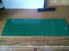
From the album: Another bum
-
From the album: Another bum
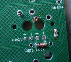
Diodes and resistors -
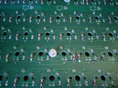
From the album: Another bum
You can see a trace that got lifted when drilling out the small holes. -
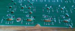
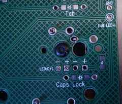
From the album: Another bum
Need to make room for the bottom of the MX switch. -
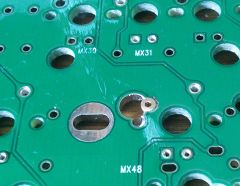
From the album: Another bum
Had to open up the pin hole to get the proper position. -
From the album: Another bum
-
 Hey fellow nerds, pc builders and home automation nerds! I wanted to share my little pet project: The pc-switch You see the device in Home Assistant and the device itself compared to a Euro coin. What does the pc-switch it do? - Control you PC via Home Assistant - Power on,off - Reset - Hard Shutdown - Monitor On/Off state - gets power over 5V from mainboard (like internal USB port) How: Software: - A simple small ESPHome configuration How: Hardware: - Based on ESP8266 - simple wifi board - power by internal pins from motherboard like USB - reset and power switch are using optocoupler to have isolation between pc mainboard and my PCB - monitoring works via the power led directly Why? - Learning (I just cant stop) - Wake-On-Lan is flaky (depends on so many things to get it working. For me it never worked) - originally for a friend who has build a 3D printed case for his PC - saving energy for your NAS/Server (does it really need to run 24/7? Turning it off for 8 Hours at night is 30% less energy consumption) - Control a PC which is not reachable like a HTPC - Automate setup for streamers (Turn on Streaming PC and Gaming PC automatically) - Get notified when you left on your gaming PC and ask for a shutdown with Home Assistant notifications - Hardware parent control. Kid is gaming to much? Just have a set shutdown time and gone are your problems (That is just a joke I came up with. Do not have kids ) - Whatever crazy stuff you would like to do Journey: I have no electrical engineering background. I just go for it. I am had a semester back in the day, but boy nothing did stick in my So take everything with a grain of salt and leave feedback if needed. It is much appreciated! First step was a breadboard prototype. Getting this work turned my brain around. For some reason electrical stuff is not easy for me. Second approach was a board soldered by myself. Man I suck at soldering. For some reason one of the switched did not work. Learned I had used way to much solder for connections. After self made thing I wanted to create a PCB version. Just for the sake of have to create a PCB (first time ever) and also making this accessible for people who do not like/know how to solder. Spoiler: I do not enjoy soldering as well Anyway. Some research later and I was trying to figure out how the heck these PCB designer programs work and which to choose from. I have gone with EasyEDA. Simple enough for my usecase. And here is the first PCB prototype: Absolut embarrassing chaos. But you know what? It fricking worked the first time! That was cool. Now, the problem was that between ordering and receiving this a few weeks have gone by. I for sure did not know which pin on the PCB I had to connect to Power, Reset, LED So this weekend I sat down and created another version with proper labels and some "branding". Will order another batch soon, therefore I just have a rendered version for you guys. If you have any questions or suggestions please feel free! I would love some feedback. Have a friend who is doing a 3D case already. Waiting for this as well. Alternatives: Oh yeah since you can only build this yourself (for fairly cheap, depending on where you live) there are also alternatives by SilverStone. But these do not integrated with Home Assistant directly. You either need to use an App with Cloud (oh my...). Or you have to go with the RF one. This one actually could be used with Home Assistant when you use a RF bridge anyway. - https://www.silverstonetek.com/product.php?pid=714&area=en - https://www.silverstonetek.com/product.php?pid=770&bno=132&tb=55 - https://www.silverstonetek.com/product.php?pid=938&bno=132&tb=55&area=en Sources: Here is the project page where you will find all information: https://www.ajfriesen.com/pc-switch/ All my related blog posts: https://www.ajfriesen.com/tag/pc-switch/ GitHub repo for ESPHome config: https://github.com/ajfriesen/pc-switch
-
My friend gave me a GPU for free. He said it was broken. I tried it and no surprise nothing happened. I took the cooler off and tried to start it again Because I wanted to feel if the chip even gets warm. But it was cold after 30 minutes. The fans and LEDs were on but everything was cold. I tried to test some resistors with my multimeter but I don't even know how my multimeter works haha. The PCB looks normal. I can't see any damage but it looks like for me that the chip doesn't get power The GPU is a MSI Geforce gtx 960 2gb v320 rev 2.0 Sorry for my bad English, Im from Germany
-
 I have a PowerA enhanced wireless switch controller, and was wondering if I could solder on some vibration motors. Could this even work? The shell has the slot for them. If this is possible where would I solder the wires to? Any help would be very much so appreciated!
-
Im not sure if this is the right section to ask this. I'm at my wits end, Gigabyte can't help me(big surprise) I've googled, ebay'd, aliexpress searched and I can't find anything. I have an Aorus c700(I know I'm a fanboy) I got this case on a great deal, and I stupidly snapped these pins off this pcb while removing the side panel, I see quite a few cases by other companies like Be Quiet!, use the same pcb to get RBG to front panels and side panels. Does anyone know anywhere where I can get this pcb? I really don't want to buy a whole new chassis. I can live without the side panel rgb it's no big deal, but if I can fix it I would like to. Thanks. (attaches pics for the one I broke and other cases that use the same one)
-
Basically I'm looking for this But with a black (possibly matte black) solder mask I wanted to make a customized pen drive with resin, but I had a specific style in mind and green doesn't really fit. Are you aware of a specific model of pen drive that I can rip the PCB out of or that is directly sold as a PCB with a BLACK solder mask? (Preferably with a decent performance but at this point, I'm accepting anything.)
-
Hi. I need to disconnect my GPU fan due to it causing trouble. However, the fan I need to disconnect (Leftmost in the image), seems to be directly connected to the all the fans' PCB connector. How do I disconnect that one fan and leave the other 2 running?
-
 Recently I was looking at a mobo ROG strix X570 E gaming on ASUS offical website . In that ASUS CPU support , there was a column named "validated since PCB" and in this column all entries were "ALL" can anyone help me what was meaning of these entries of vadiated since PCB column!! Here is the link -https://www.asus.com/in/Motherboards/ROG-Strix-X570-E-Gaming/HelpDesk_CPU/
-
 Air Cooling the back of your Motherboard?! So i was wondering if any of you have had any first hand experience with air cooling the back of the PCB on your motherboards with a small to medium sized fan like an 80mm for example or if you have read/seen any tests on the topic? Does it have any positive effects on your CPU/VRMs and such in terms of overall temperatures? And which direction should the airflow of the fan be pointed at? Blowing air onto the surface or "sucking" the hot air away from the PCB? Of course the design and airflow capability of your case especially in the region behind the MB does have a big impact on the results i suppose, and it will be very different for everybody. Does this concept make sense at all or is it a total waste of time? So let me hear your thoughts on the topic! cheers
 -
 Hi all, I am attempting to repair my first GPU that I have purchased on ebay(ASUS GeForce GTX 1060 6GB Expedition Boost). I know its not the best idea because it might as well be a dead GPU, but i have gone for it anyways The GPU warms up with not display detection. I have checked the ram voltage and GPU voltage and it all seem to be fine with VRM running at 1.4V and GPU mosfets at 0.7V. Hot Component Later, I realised that my transistor is warm but then this component(arrowed above) running at 5V is really hot instantly which makes me worry, so I have de-soldered it and I am looking to identify it for a replacement. Any Ideas?
-
Hey everyone, I just removed the back plate of my graphics card for some late spring cleaning and discovered an oily substance on the PCB. I guess it came out of the thermal pads judging by the pattern. Any idea what this might indicate?
-
 Basicly the title, My primary drive PCB cought on fire and I would like to try to recover the data for as cheap as possible. I was informed by reddit that simply replacing the PCB with one from an identical drive won't work. Any ideas on how I can recover my data or am I better off just starting over. HDD specs: Seagate Barracuda 160gb 7200.12 (st3160318AS)
 -
 Hi everyone! A couple of days ago i've purchased this sentey case very cheap because it's fan controller doesn't work. I've opened it to see what was happening and i they tried to solder replace pieces in the fan controller pcb (and they've done a really bad job). So i fix that BUT the guy also cut off the cables and now i've got the PCB alone without the cables to the PSU, Fans, etc. So i have the board connected to the potentiometer and i need to know where to solder and connect the rest of the cables
 -
Hi! Recently my Gigabyte GTX 1070 G1 Gaming (rev1.0) has had a mosfet catch fire I want to repair the board, as I will send it to a store specialized in this kind of repair, but I need the model of the mosfet that blew off, if someone is kind enough to provide me with a high-res photo of the interested area (pictured in the attachments) I would be so happy! I tried asking on reddit, but got no luck, I opened a ticket to gigabyte, but they couldn't help as the card is out of warranty. Thank you for reading
-
So, i'm kinda new to dealing with electronics, sorry for being a pleb I was cleaning the rust off of one of the switches so I could desolder it (that's a whole other problem that i won't go into) and I accidentally bumped into a microchip with the soldering iron and it went flying, now I can't find it. Now the LED's that are supposed to be on on the WASD and arrow keys don't turn on. You can see in the image what kind of microchip that fell off. So i was wondering if that piece is something that i can buy and solder on, or is it a chip that i can't buy separately.
-
Hey Guys/Gals, I placed it in this part of the forum as it appeared to be the most Apt, but i've been wanting to learn how to solder electrical components for sometime now and i have finally gotten around to doing it. Ultimately i want to be able to restore and modify retro game consoles beyond the thorough cleaning which is what i currently do. So soldering/de-soldering capacitors, chips, wires etc... That being said i was wondering if anyone had any suggestions regarding any practice material that may be available. Given my first ever attempt at soldering was replacing voltage regulators on a genesis i had as a kid, which i botched horribly, i would like something that i can tinker with that doesn't make things a lot worse. I already have a fair amount of tools typically needed such as the soldering iron, flux, flat snips, multi-meter, and even one of those quad hands. I appreciate any suggestions you may have.
-
Hello there fellow PC enthusiast! (tl;dr at the bottom) First off thank you for clicking on my thread, because I'll be needing any and all help I can get and any info at all would be great. Okay so I was browsing a certain popular New Zealand auction site and I found a deal. The deal was for a Radeon HD 7970 $30 NZD, faulty. So I decided to take it upon myself to repair it. I am already running a Gigabyte Windforce GTX 670. I have never repaired a GPU before so I am pretty much a level 0 noob at repairing this type of thing. But I am %110 willing to learn. I've made an imgur album with all the pictures, and don't worry there is no such thing as a potato quality camera on the Note 4. The guy I brought it from stated that.. "Found out that the previous owner had baked it but didn't know what he was doing as he most likely left it in there a bit too long. I would think about 2-3 hours and a steady hand to resolder some of the components down and you would be good to go" Once I received the GPU I put in my system and powered it on only to find that the fans spin, the logo shines bright and it doesn't display. So the dude who sold it to me was an honest one and didn't sell me a completely dead GPU only to say no refunds, thank the non-existent god I don't believe in. I have taken apart GPUs in the past to clean/reapply thermal paste so it was a relatively easy process. Upon first glance I saw no exploded capacitors or burnt out microchips. I took off a metal cooling bracket to find the problem. A series of small silver microchips had become de soldered, I guess when the previous owner put it in the oven. My guess is that that the chips solder melted and due to the placement of the GPU fans down they came slightly away from the board. Thus making it even more dead. Any help would greatly be appreciated. If you've gotten this far thanks for reading my post. Leave a comment with your thoughts. Links: GPU Specs: https://www.cnet.com/products/sapphire-vapor-x-hd-7970-ghz-edition-graphics-card-radeon-hd-7970-6-gb/specs/ Imgur Album:http://imgur.com/a/IhhkC Tl:Dr Microchips on the board have been heated up in the past. The have fallen off, how do I re solder them back on/ check to see if they still work?
-
I want to water cool my GTX 1070 but I don't know what heatsinks to get. I already have the g10 and the corsair h55.
-
So this is really strange. I accidentally touched the back of my PCB after gaming and it was WAY too hot to touch. I took my thermal gun out and found that it is getting up to 231F near the middle edge of the card where the power goes in. Right where the power goes in is 187F. The back of the GPU is at 114.5F. I've had an EK waterblock on it for about 6 months without any issues. The temps stay in a great range. My core temps never go above 33C while gaming and it is overclocked to 1500mhz on the core. I don't think a backplate would help as the temps around the PCB look great. It is just near where the power delivery is. I have 2 - 480 radiators in a Corsair 900D. Any thoughts would be greatly appreciated! This is a picture of my card without the heatsink. I see some caps there. I highlighted the area on the right side where that 225-231F readings are coming from. Also, here is the waterblock I'm currently using. It isn't supposed to connect to that section of the video card as you can see there are cutouts to make room for the caps.
-
Just wanna know if the gtx 1060 (founder's edition) has similar PCB design like the 1080 has (same mounting points for the reference cooler). And also if the gtx 1060 gigabyte windforce OC(the one without backplate) has the same mounting points (I want to put a reference cooler on it).