


F.A.T.
-
Posts
79 -
Joined
-
Last visited
Content Type
Forums
Status Updates
Blogs
Events
Gallery
Downloads
Store Home
Posts posted by F.A.T.
-
-
- Popular Post
- Popular Post
Since being a goldsmith has not so much to do with making a computer, I have been busy making a piece of jewellery I could wear at the computex ;) . A silver keyboard ring with my initials on it. If you would like to see how I work as a goldsmith....again.... just scroll down ;) !
I made a wax ‘Ideal’ keyboard key and casted in brass. Then I made a rubber mould and made more wax keys.
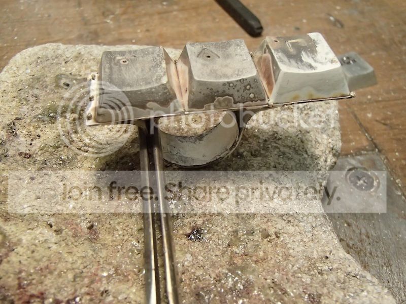
These keys were casted in silver, so you can mass produce silver keys ;) !

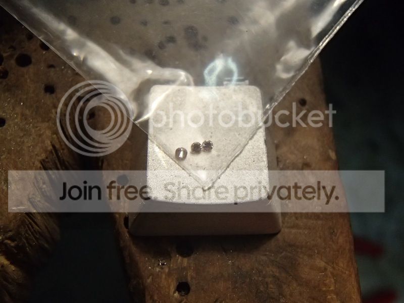
Here you can see the casts.
This is what I want to engrave.
First finish the keys.
My logo.
I still had 3 tiny diamonds which I will set in the ring.
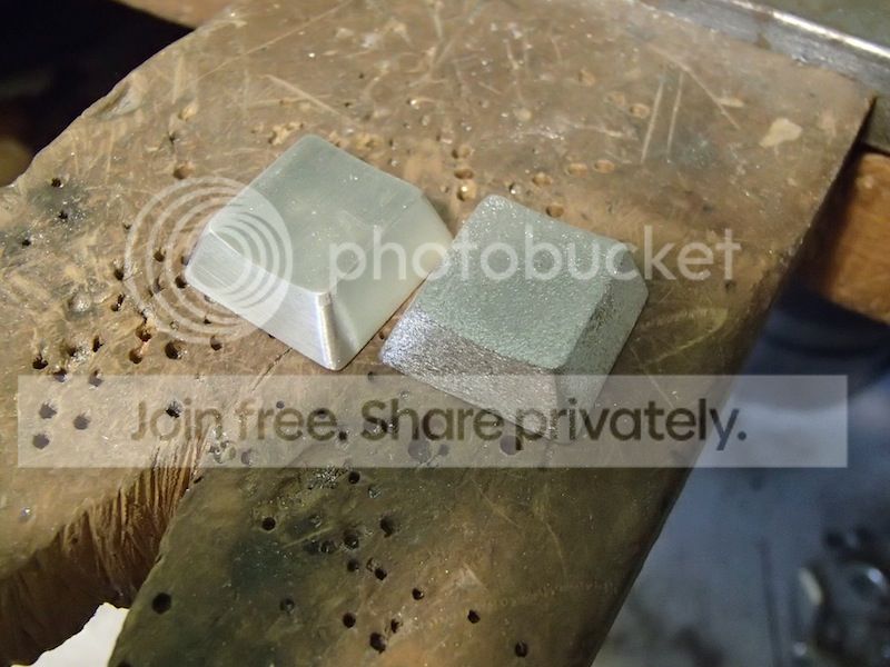
Here you can see different surface techniques.
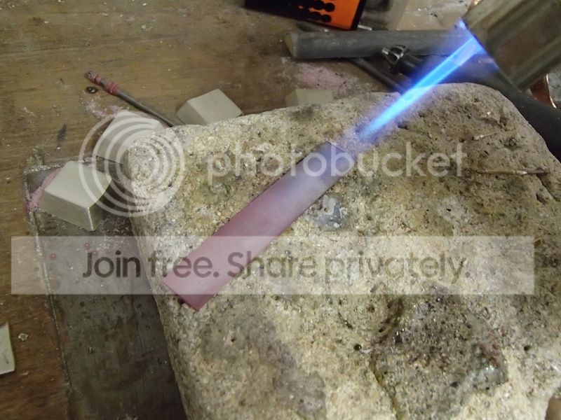
I have enneald the silver so I can bend the material easily
Then bend the silver and solder it together.
To make the ring round you have to hammer it.
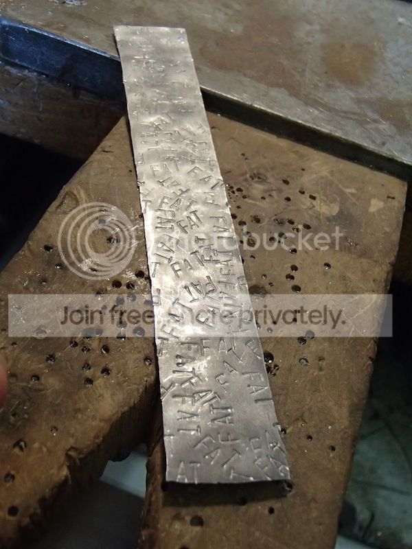
To make the backside of the ring more interesting I have stamped my initials in the silver plate.
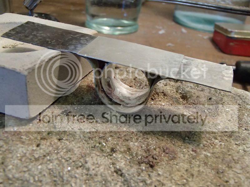
First I started with drawing on my logo. I made a ‘light’ engraving with my milling tool (sort of dremel).
To cut away the logo I used a engraving tool.
These 2 elements will be the frame of the ring, I will have to solder them together.
A silver plate that goes across the gap so the keys will stay in place when I lay them on, and solder them.
After you solder the silver there are a lot of oxides, so I always use a chemical to clean the material. It makes the silver look snow white.
Cut away the extra material.
One of the diamonds, they are so tiny!
Soldering everything together.
I wanted the letters and my logo to stand out more, so I used a chemical which makes the silver go black. If you sand the material afterwards the lower parts will not be schratched so will stay black.
Now only finishing and than set the stones.
And the final result!!!!
Hope you like it!
I also made a few goodies with me to Taiwan to hand out to people there. It was a very interesting day ;) !
The lasercutter.
First a few testplates.
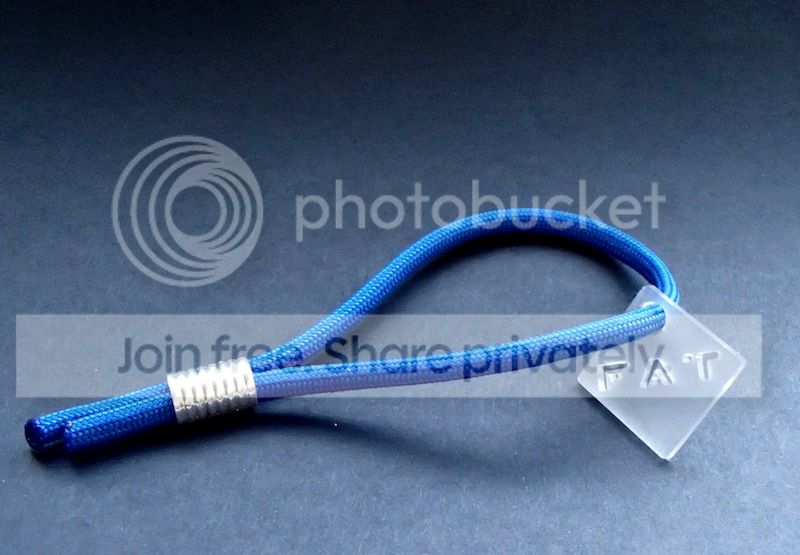
The real stuff ;) !
The lasercut goodies :)
Interesting day :D !
I’m very happy with how the build turned out! If I would have had more time and knowledge that I now have, I would have perfected it.
But I’m already thinking about my next project, so maybe soon there will be a new buildlog ;) !
-
After this I went on with the polycarbonate plates. I wanted these to sink into the frame nicely so I had to cut away the edges. which meant..... One big mess ;) !
I cut away on every side of the plates 1mm of material so the frame (which is 1mm thick) will fit exactly.
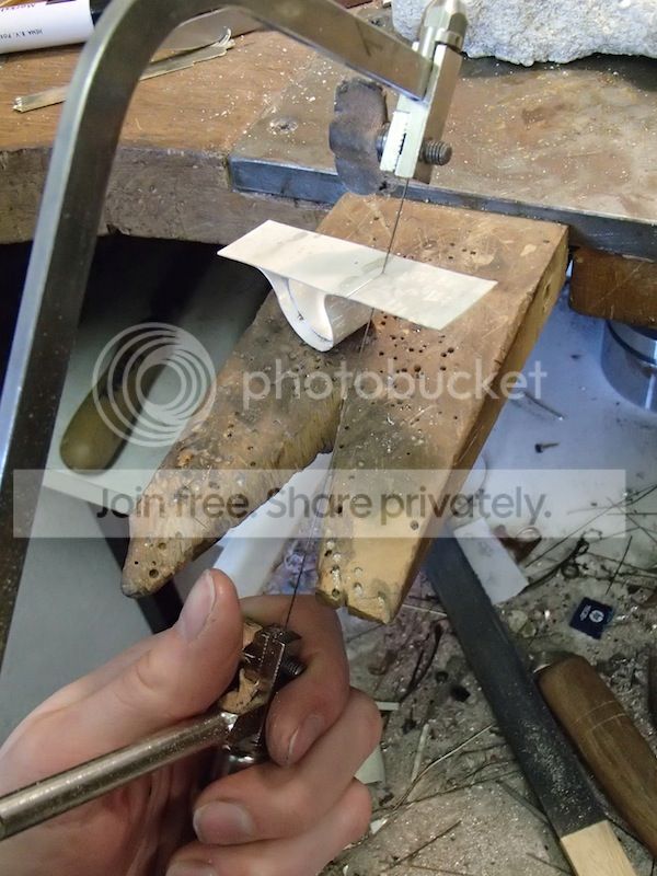
Here you can see that I’m cutting the poly carbonate plates. I fixed them so I can easily cut away a straight line. you won’t see the suface when the plate is fit into the frame.
I gave both of the plates the same frosted texture. The light of the LED’s will spread nice and evenly because of this surface texture. It wil diffuse the light.
I used my diamantpowder tool to scratch the surface. It takes quite some time but I was really pleased with the results.
Difference in surface textures.
lots of work ;) ..
Takes a long time...
Also a small testplate of aluminium.
When I finished both of the plates I could glue them with 2 components glue.
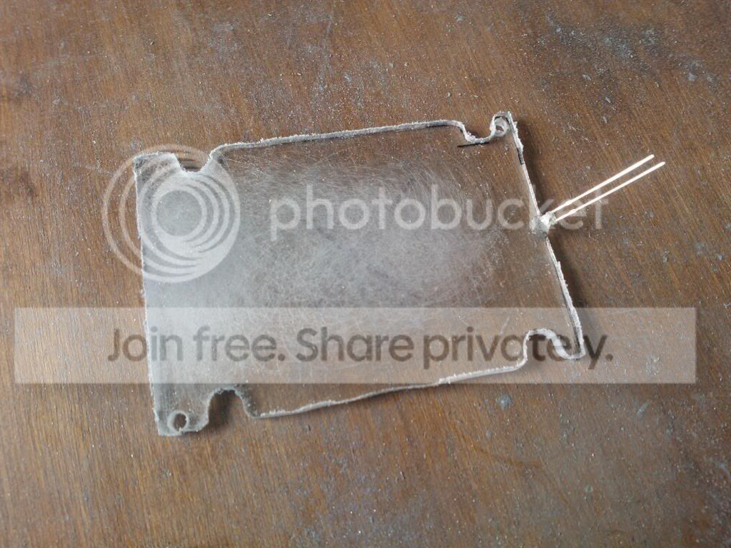
On the backplate there will be the harddisk. This will be covered by another smaller plate. there will be a gap where the cables can enter and exit the harddisk. In this smaller plate I will also apply LED’s so it matches the design.
I made a harddisk holder from aluminium angled profile.
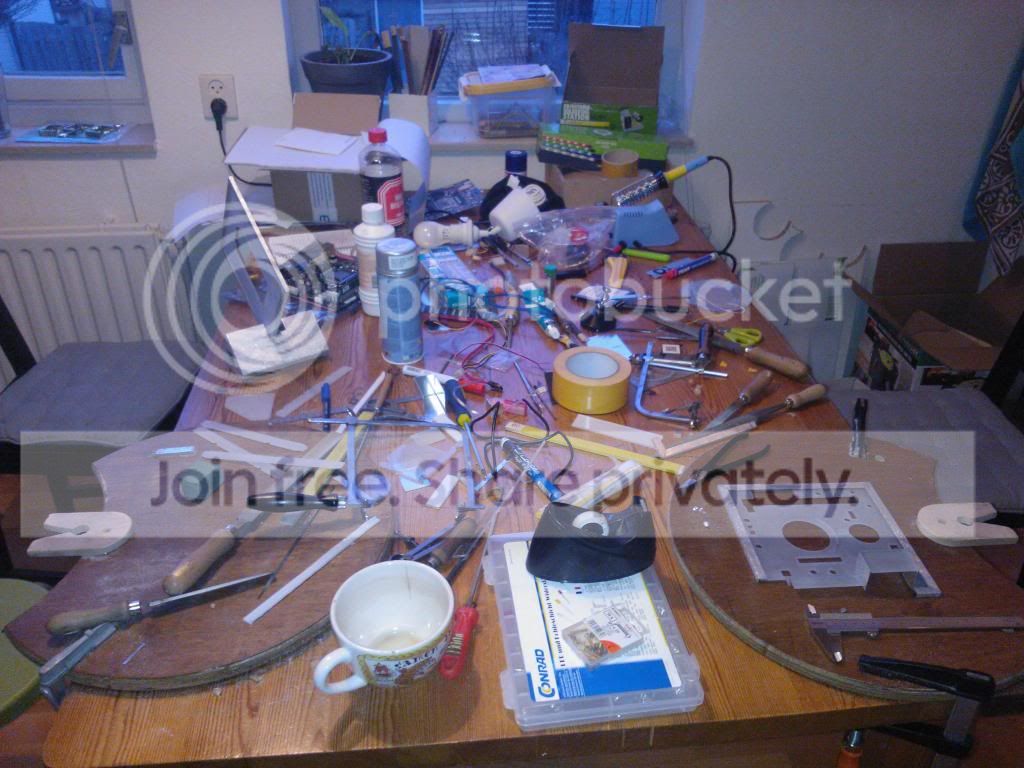
Meanwhile my kitchen table looked like this... ;)
Here you can see the harddisk plate with the LED’s.
In the frontplate I will add some LED’s this makes the build more exciting when the computer is turned on.
Here you can see 4 LED’s, soldered and (ofcourse) tested ;) !
These are the LED’s in the base of the Build.
I fixed the LED’s in the base with.... a lot !!! of glue.... Not so pretty but, it works ;).
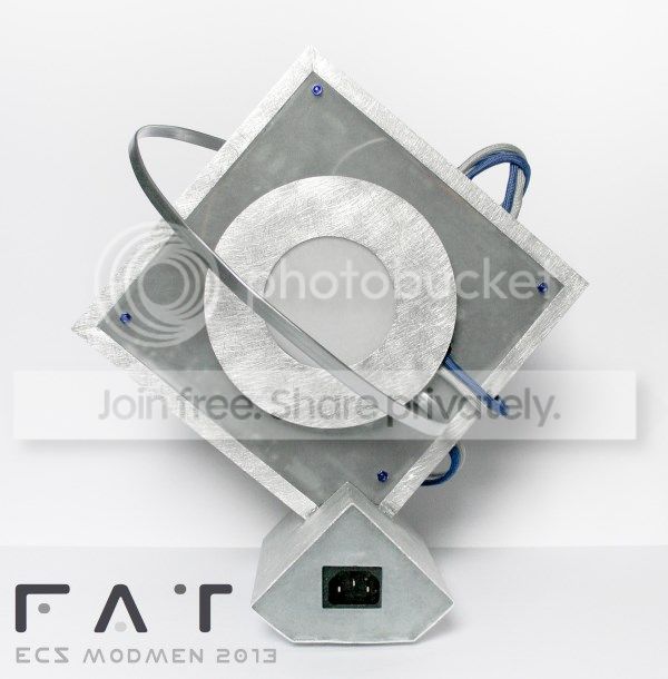
Here you can see how I attached the adaptor to the base.
Anddd... its gone.
The poly carbonate front plate exists out of a lot of small pieces all put togeter. All of the key features on the motherboard have their own modified ‘sockets’.
Here you can see I disfigured a Pico PSU ;) . I wanted to make a case for the PSU and sleeve the cables with paracord to make it look really nice.
Here you can see where the cables are suppost to come out of.
This is the RAM- cooler I made. 2 small plates which cover up the RAM. The top is made of poly carbonate and I will add 2 LED’s there so the RAM will light up.
Finally the frontplate is coming together.
Ofcourse the Fan also had to go through a lot in this Build.
I took an old fan apart and made it shorter. Don’t worry... It will look nice in the end ;).
Taking the fan apart...
I made a small groove in the CPU cooler so the fan fits in perfectly.
Than finishing touches, spraypainting the fan.
This is the moment where I put all of the small components together to make the build complete.
Here you can see that the LED’s are in place and soldered.
First test run...
Luckily everything worked! Now I had to keep all of the cables in place because there is only limited space left on the sides of the case. (I used hot glue to secure some cables... I know.. not pretty ;) )
First time putting everyting together!!
Putting everything together with, glue ‘my-best-friend’ after this build ;). The cables haven’t got sleeves yet.
After fitting in the motherboard, I started building everything up.
Clicking everything together and sleeving the cables. I spraypainted the sata cable silver.
Here you can see the lack of space for the cabels ;). I was very happy that everything fitted !
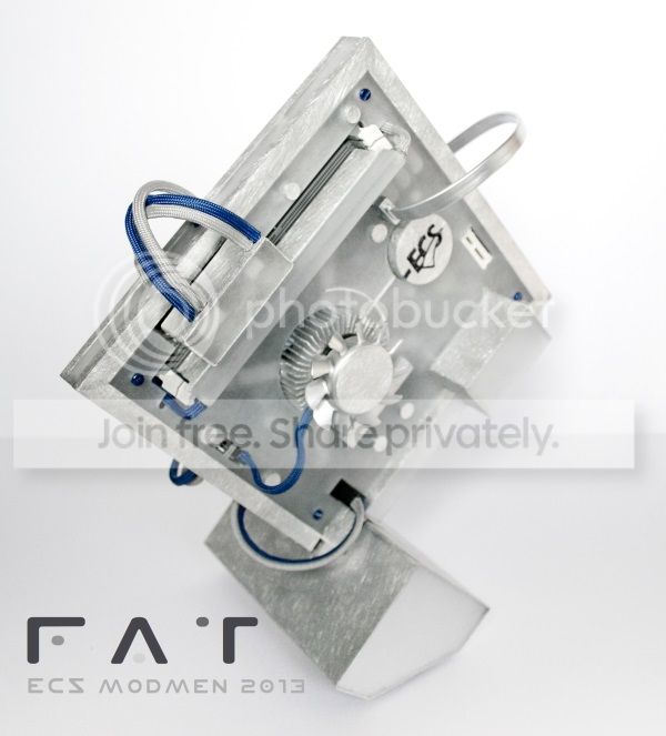
The front and backplate of the build are attached to each other by 4 small screws. So the motherboard hangs in place in the build.
This build is especially very compact. It is 22cm high, and the case surrounding the motherboard is 19,5 x 19,5 cm and 2cm thick.
-
Hi everybody!
My name is Femke Agnes Toele, in short F.A.T. I’m a goldsmith and silversmith by profession and I have a small workshop at home where I can work.
I have a lot of tools at home, and make a lot of things, not only jewellery. I have always been interested in electronics but never really got the chance to master this.
So when a friend of mine saw the ECS Casemod Contest on the internet, he said that this could be the chance for me to work with both electronics and a nice design.
I thought; ‘ I’ll give it a try, (not knowing that It would turn out really well : ) !
I went to Computex Taiwan last week to promote my computer with 4 other Modders. Great experience and I won the ‘Viewers Choice’ award on top of that!!
This is my first scratch build. So if you want to see how I made the build.. just scroll down : )
My Mod is called “Little Scratch”, it is a very compact build. The build is 22 cm high and the case around the motherboard is only 19x19cm.
I made a video for the Contest, if you want to take a look, here is the link:
BUILD LOG:
I started to make a few designs out of cardboard just to get an idea about the size of the build.
Immediately I noticed that I liked a smaller design. So in the end I didn’t use any of these designs, and I started with someting else.
A friend helped me with the basic computer knowledge and made me some styrofoam blocks in het shape of the MB, PSU, etc. So I could start to puzzel with all of the parts and give them their place in the build.
I printed an image of the motherboard that I used several times to highlight the main features of the motherboard. In this contest the motherboard really had to stand out!
After I made the design for the build and decided on what hardware I was going to use I ordered everything.
The Motherboard
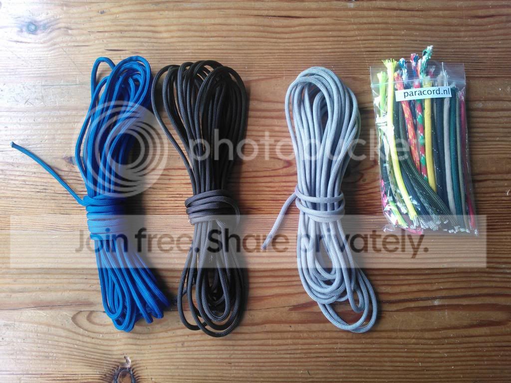
Paracord To sleeve all the cables.
A box full of LED’s, always good to have!
The Processor
And a Pico PSU!!
Ofcourse the RAM
An old fan
So now the most fun part of all, starting the Build : )!
The plates which will cover up the motherboard are made out of poly carbonate. This material is also used in bulletproof glass. It will bend but not break when you cut it.
First drilling the holes and after that cutting away the parts.
Here you can see that the poly carbonate plate almost fits on the motherboard.
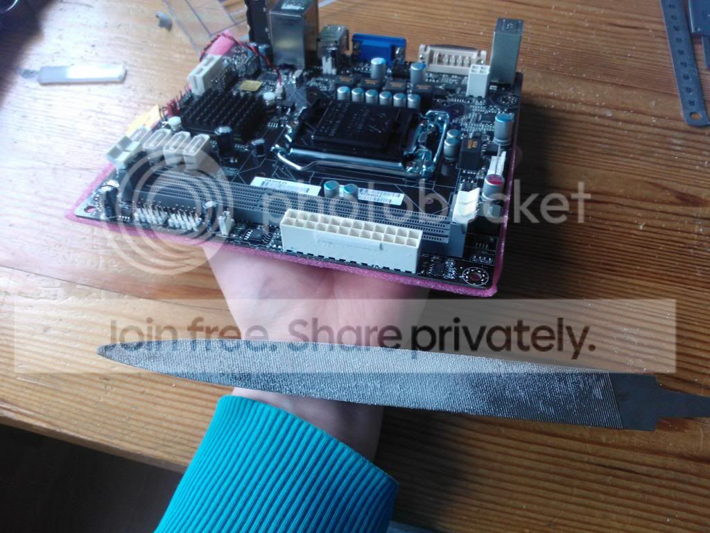
I had to modify the motherboard a bit to make the front poly carbonate plate fit. I used a file to cut away a few edges.
For the Mosfeds and capacitators I made small aluminium coolers. They will show at the front plate of the build.
The Heatsink I wanted to use was very big and not really....good looking. It would cover almost half of the motherboard if I would have left it the size it was.
I cut it untill it was only 5,5cm in diameter. I did this with a disc cutter. To make the Cooler nice and round I used a Turning Lathe.
The Chipset cooler is made from a solid piece of aluminium also made on the Turning Lathe.
I made a special frame for the cooler to fit to the motherboard.
Under the heatsink I also solderd a solid frame, which is quite difficult because you want to have your heatsink exactly on the processor when you screw the part to the motherboard.
To make the last cooler look nice I engraved the ECS Logo.
After I cut the Logo I filled it up with a Blue paint.
I had to make a frame for the motherboard. I wanted to keep the build as small and thin as possible. I bought some aluminium angled profile and cut these to the right size. Made angles and solderd the frame together.
Here you can see the aluminium solder on the corner of the frame. This type of solder doesn’t ‘flow’ like normal solder does. It is very strong, but I only cut away a little of the extra metal. I will modify the front plate of polycarbonate to the frame.
The aluminium has a special coating. I wanted to take this off to let the aluminium shine more and give the material a more ‘metal-looking’ look. Here you can see the differences.
To create the base of the computer I took a sheet of aluminium and folded this into the right shape and soldered it.
The frame has to be held by the base so I cut a hole in the base. One of the corners will sink into the base to create a stable form.
The base is quite light, so to give more weight to the build I made some pewter blocks to fit in the base. The blocks will be tightend to the bottem so the case is stable and will not fall over or anything.


First Scratch Build - ECS MODMEN CONTEST
in Build Logs
Posted
Thanx for the comments :D