rhyseyness
-
Posts
2,229 -
Joined
-
Last visited
9 Followers


Recent Profile Visitors
3,067 profile views


rhyseyness's Achievements
")
-
Been trying to buy a 1660 super for the last week. They've all sold for >£130. I'll see if I can get an rx580 or 1060, cheers all!
-
Budget (including currency): £100 (GBP) Country: UK Games, programs or workloads that it will be used for: Primarily gaming Other details (existing parts lists, whether any peripherals are needed, what you're upgrading from, when you're going to buy, what resolution and refresh rate you want to play at, etc): Currently building a PC for my partner as a Christmas gift. Have been buying parts used to keep the cost down. Need advice on which graphics card to buy. Looking for the best graphics card that can be had for £100 used Hopefully simple enough! Thanks in advance!
-
They're aluminium caps which have a lifetime- Usually they last about 10 years before needing to be replaced. If you're not electronics-y, I'd recommend you buy a new PSU rather than replacing them.
-
So I recently got an MSI Gaming trio X 2070 super. Starting doing some overclocking the last couple of days, and I've found that no matter what I do in afterburner, the card won't go over 65°C. It happily sits at 2100MHz until the temps hit 65 (which happens quick), and it then downclocks. The thermal limit in afterburner is set to 88°C, and the fans never even get to 30%. Furmark benchmarks run fine, but obviously with lower scores than expected because the card downclocks. Any ideas? Thanks in advance! EDIT: Nvm forgot to enable voltage controls in afterburner, all good now
-
This thread is what makes this forum so great. Nice work @JayBee805! Enjoy your shiney new PC
-

Circuit Broad Capacitor Replacement
rhyseyness replied to Mr.Monkeyface's topic in Hobby Electronics
If this is a measurement out of circuit, looks like the resistor isn't dead. Dead resistors will read open circuit (>2Mohm). Massively unusual for them to fail and read anything other than short or open. As @Unimportant quite rightly says, you could be measuring something in parallel. This is not true. You'd definitely need to replace a 0 ohm resistor because it forms a connection in your circuit, just like a wire link. If a wire link snapped in half, you wouldn't say "you shouldn't need to replace it," haha.- 17 replies
-
- 1
-

-
- circuit broad
- question
- (and 2 more)
-
[Finished!] Wall Scale Graphic Equaliser Build Log
rhyseyness replied to rhyseyness's topic in Hobby Electronics
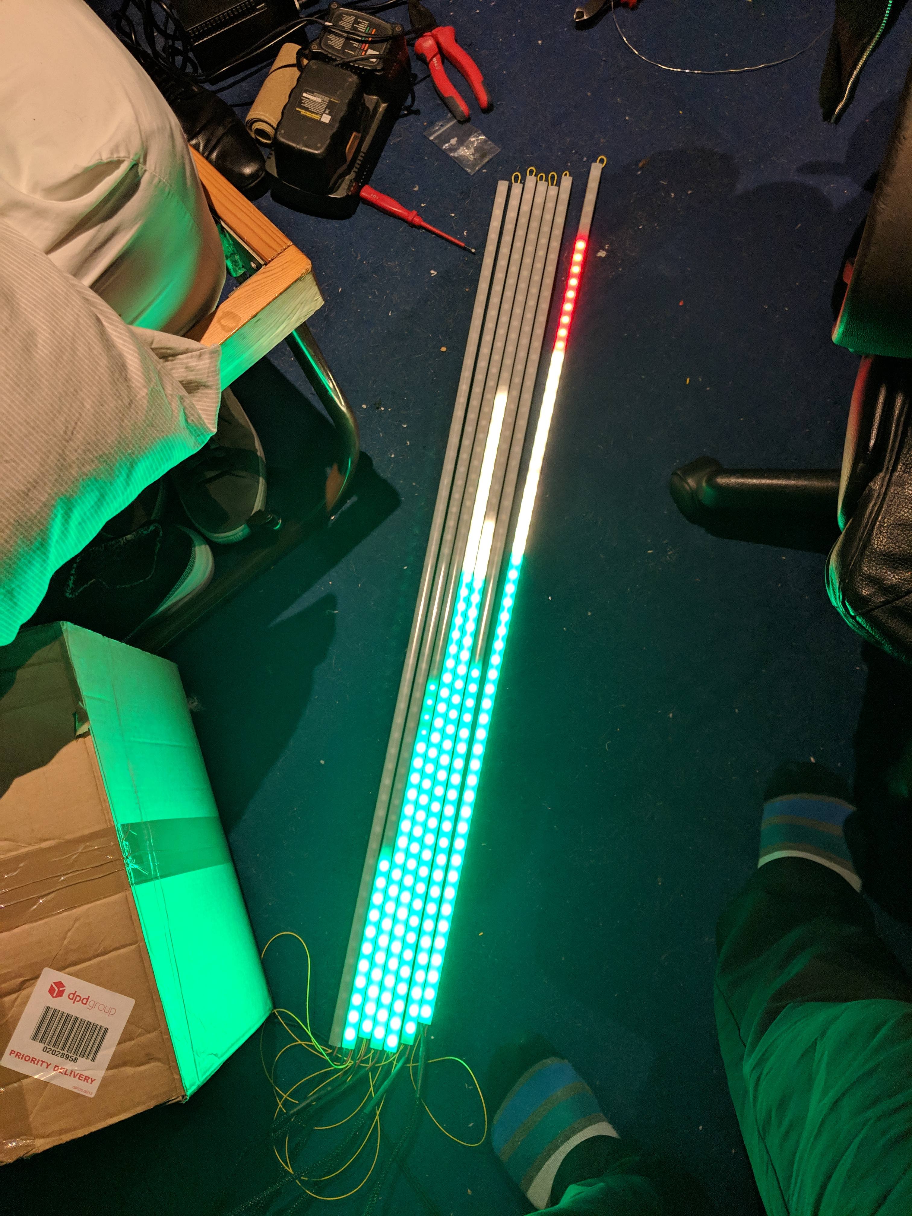
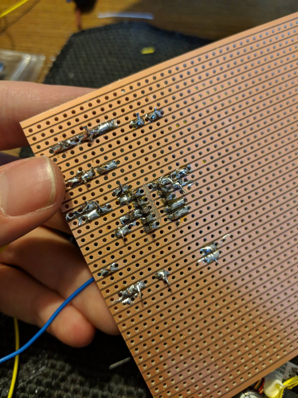
So after a few setbacks, it's finally done and mounted on the wall! I'm really pleased with how it's turned out. Had to change all my data wires over to something less stiff, but now they don't pull the pads off the strip. Video of the finished product mounted on the wall here: https://photos.app.goo.gl/1PmAuumD8c7UsFJf9 Some photos too:
-
[Finished!] Wall Scale Graphic Equaliser Build Log
rhyseyness replied to rhyseyness's topic in Hobby Electronics
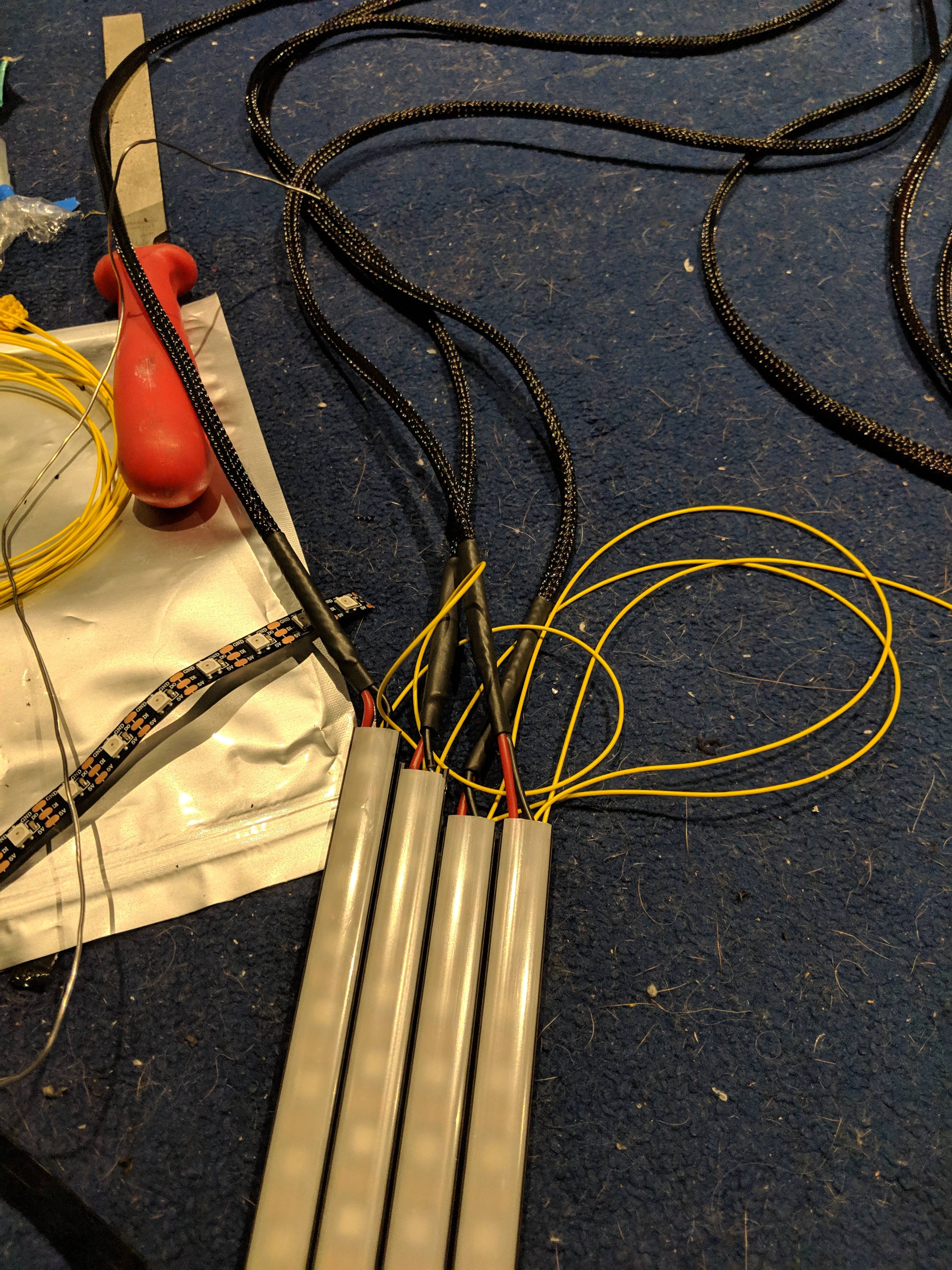
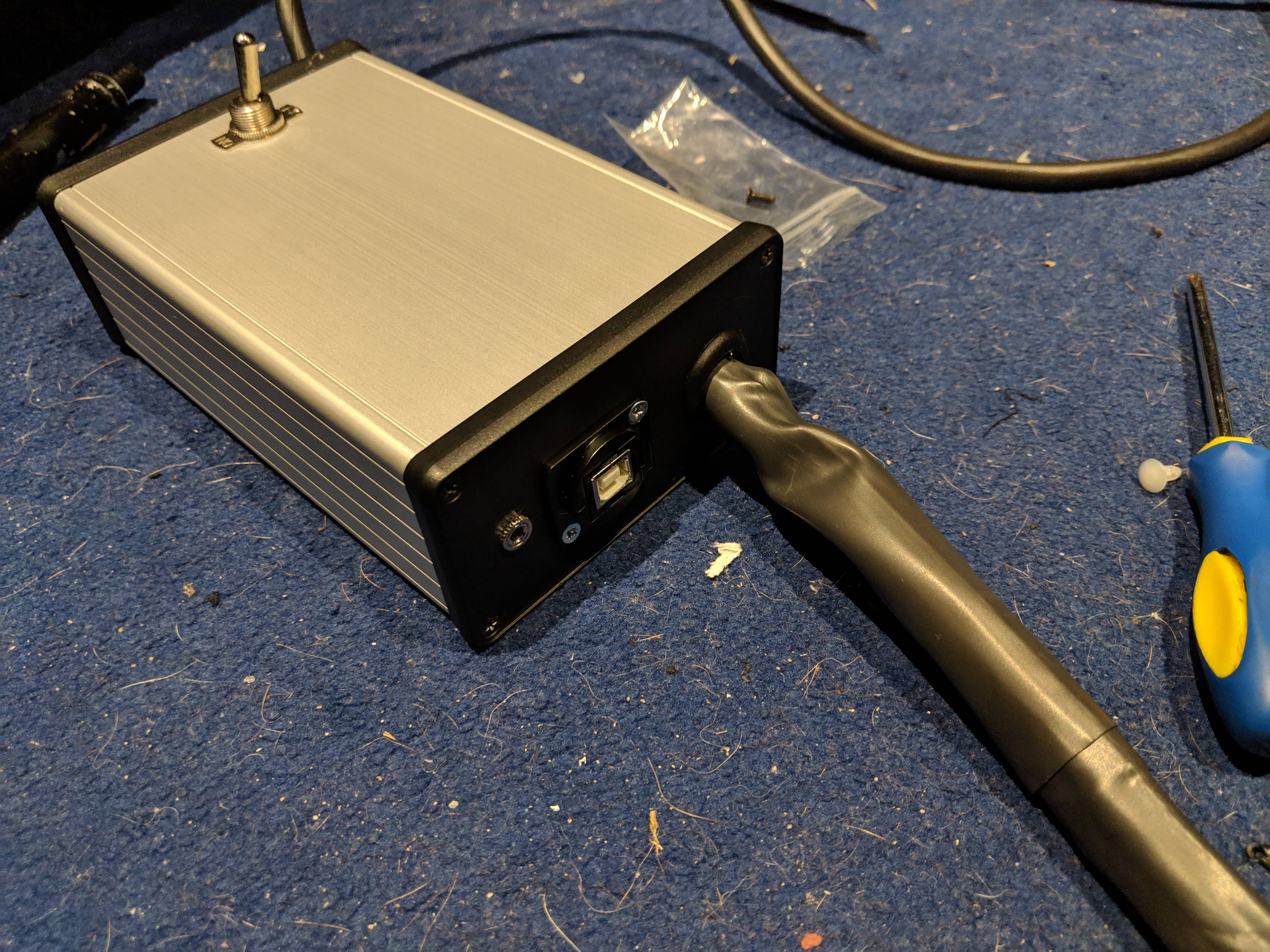
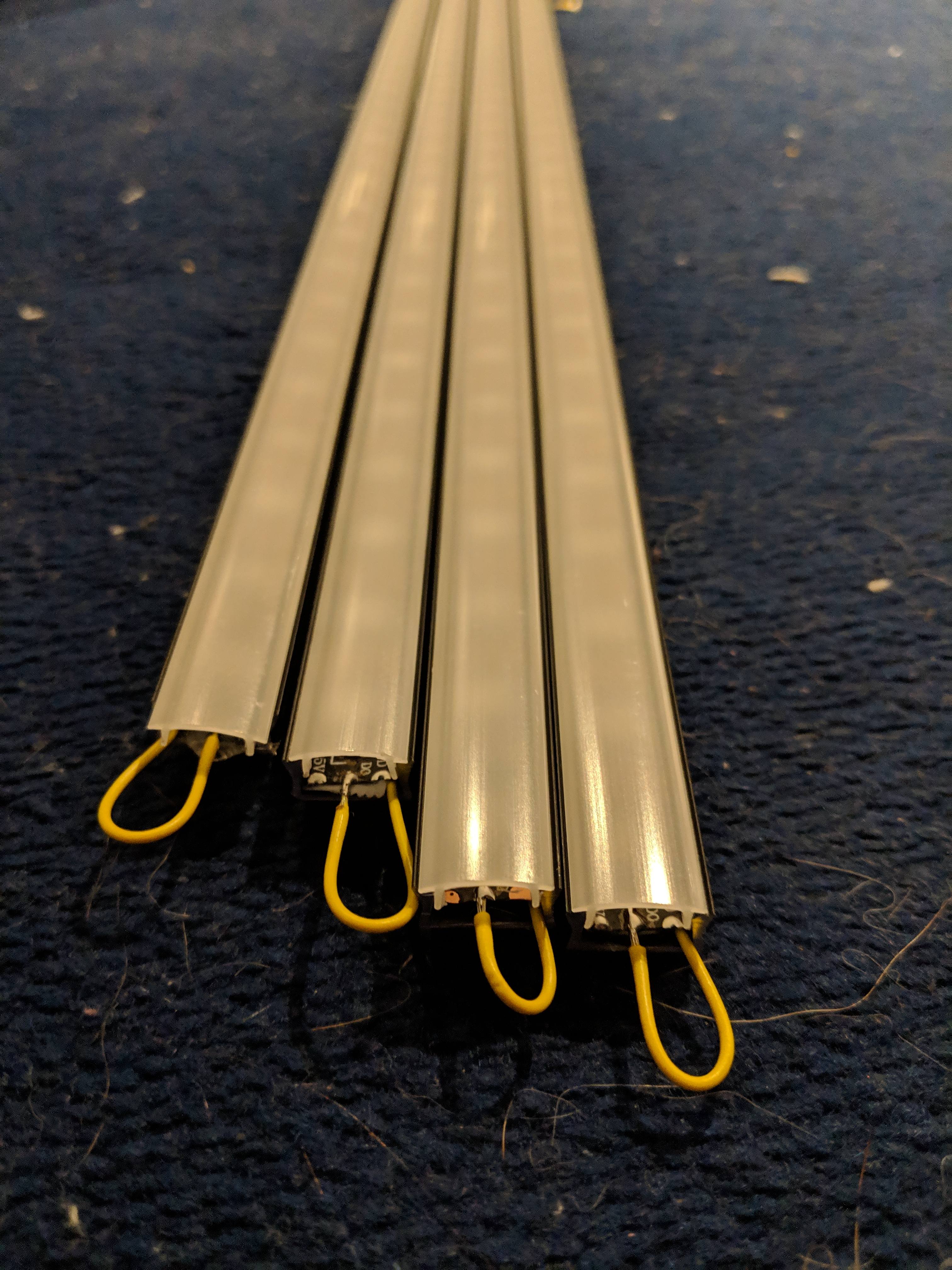
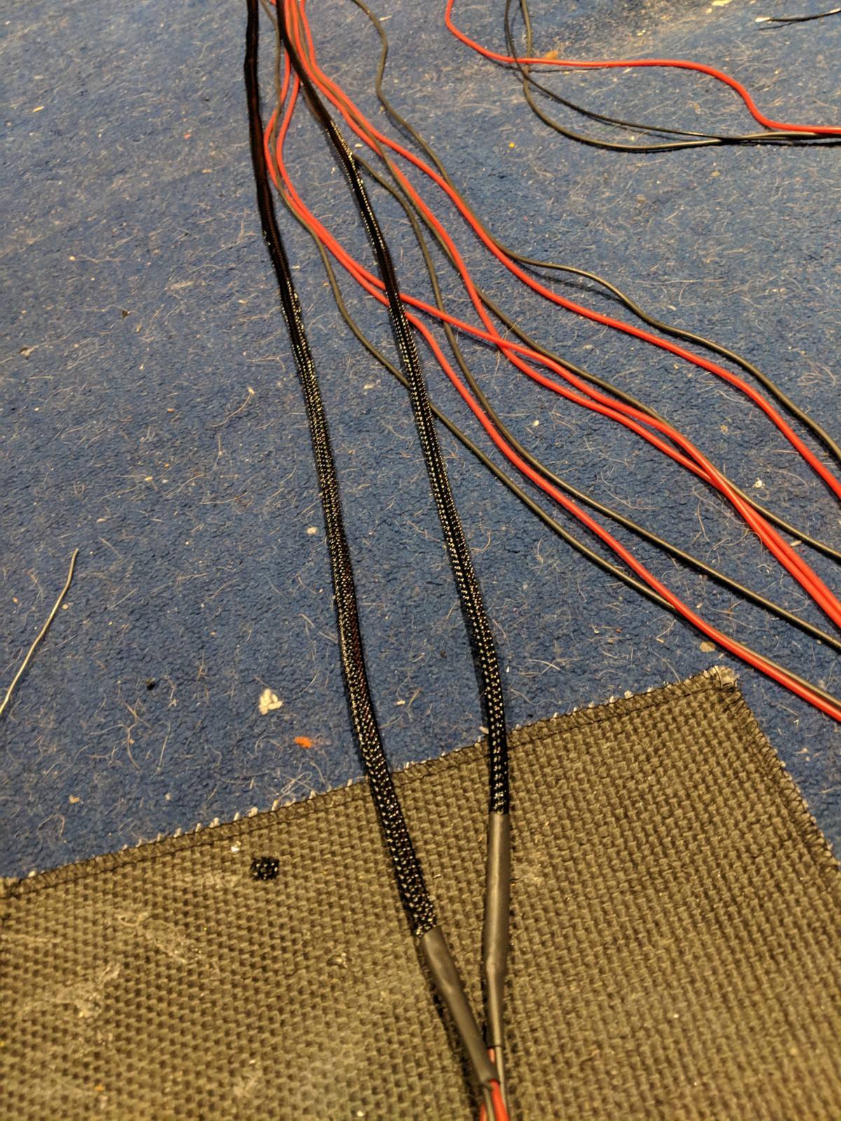
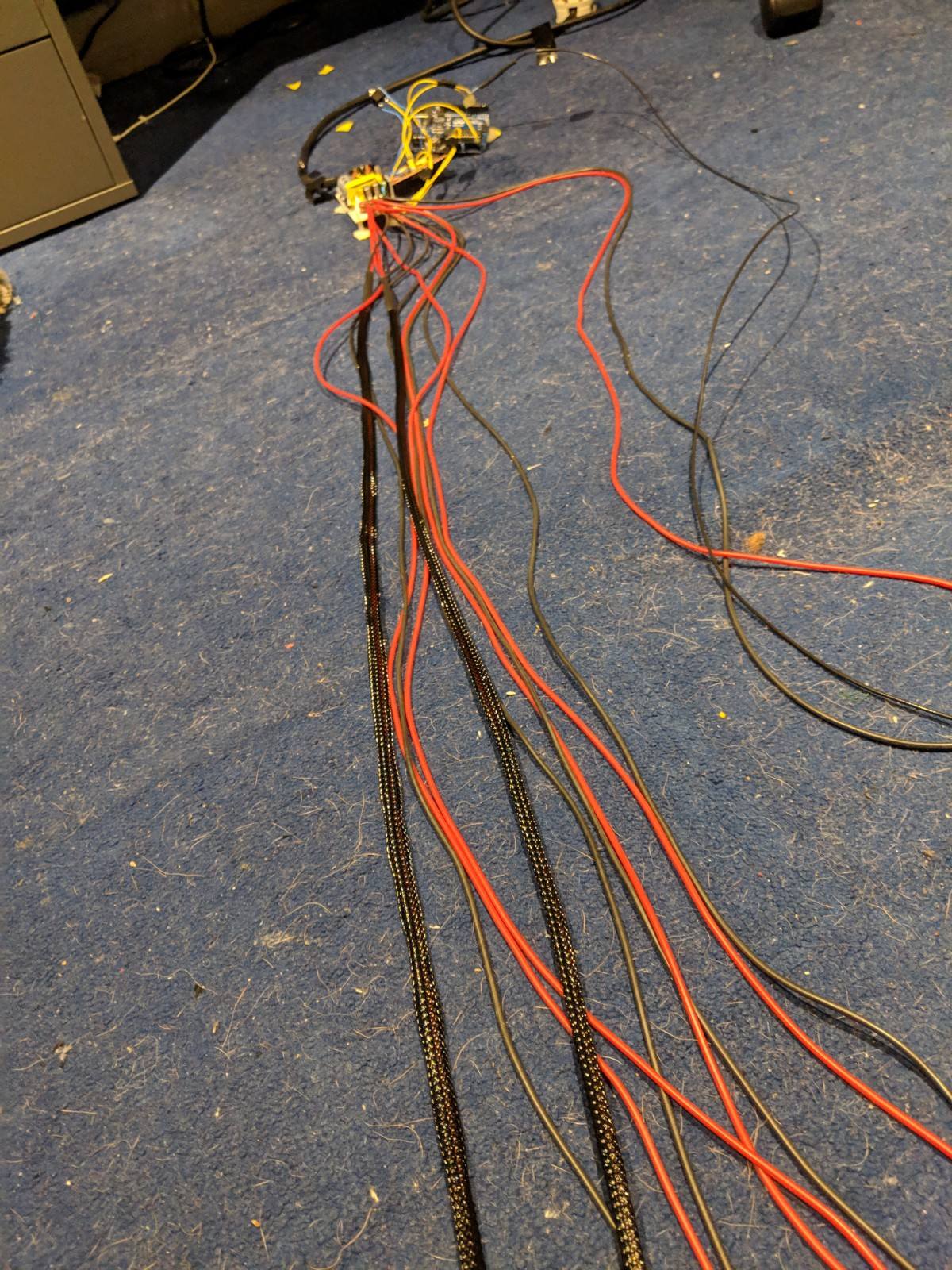
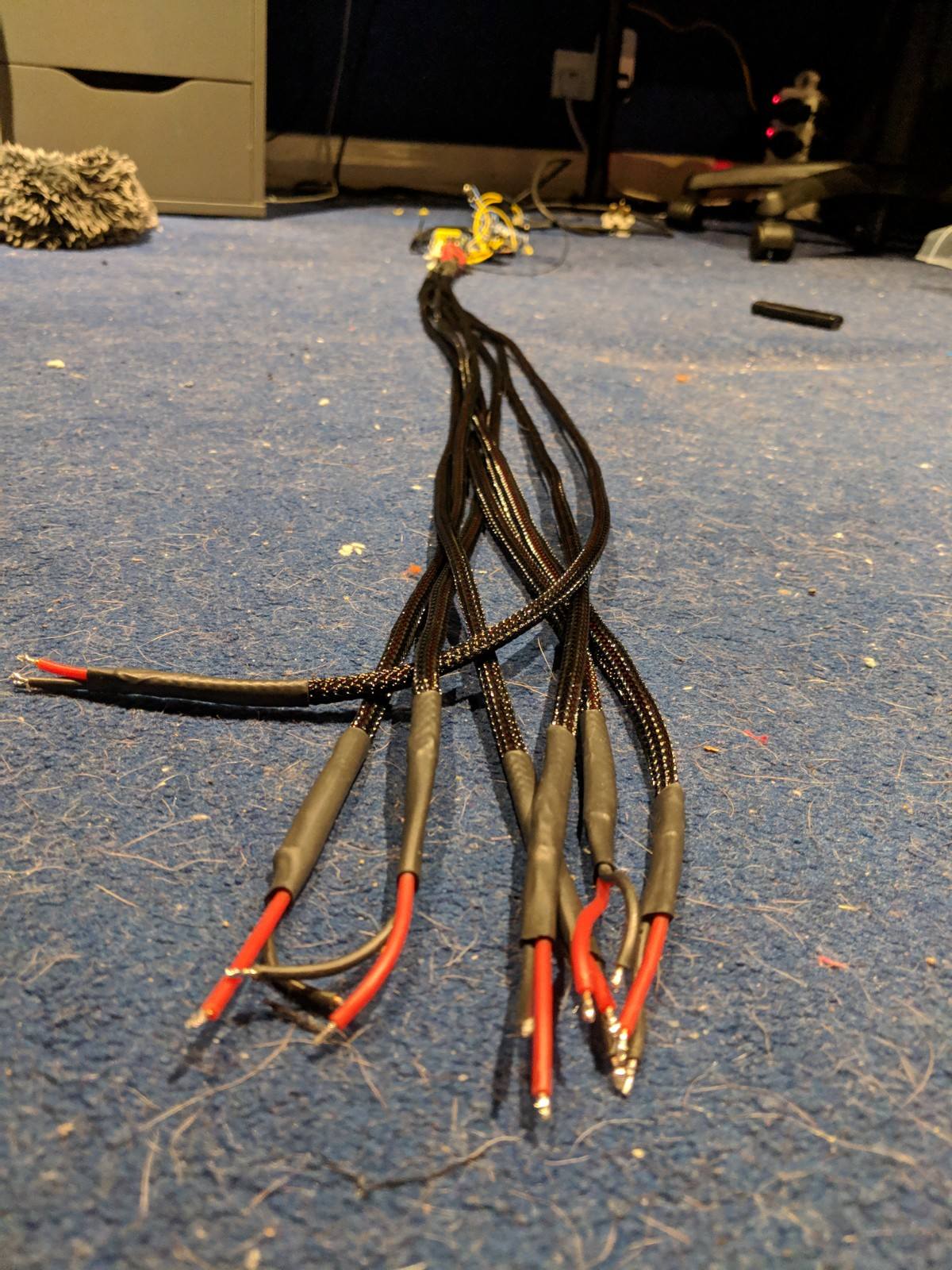
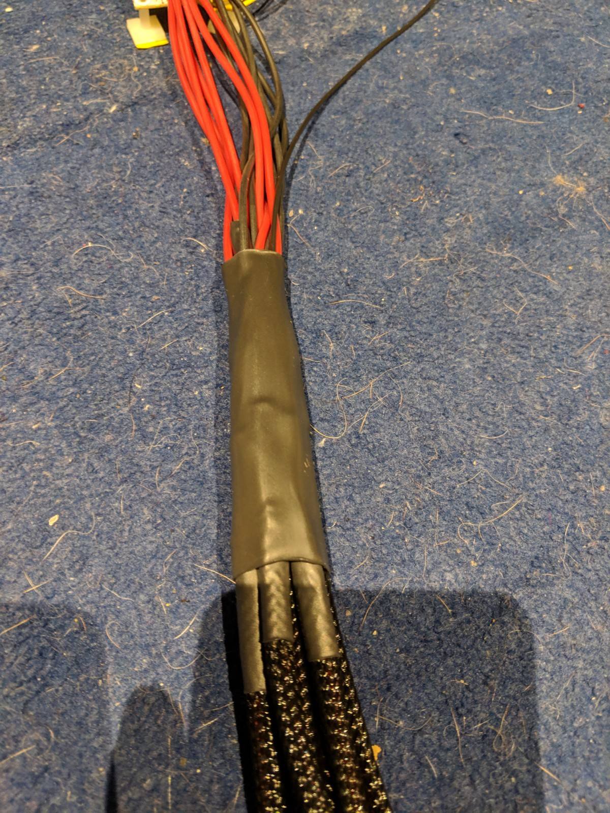
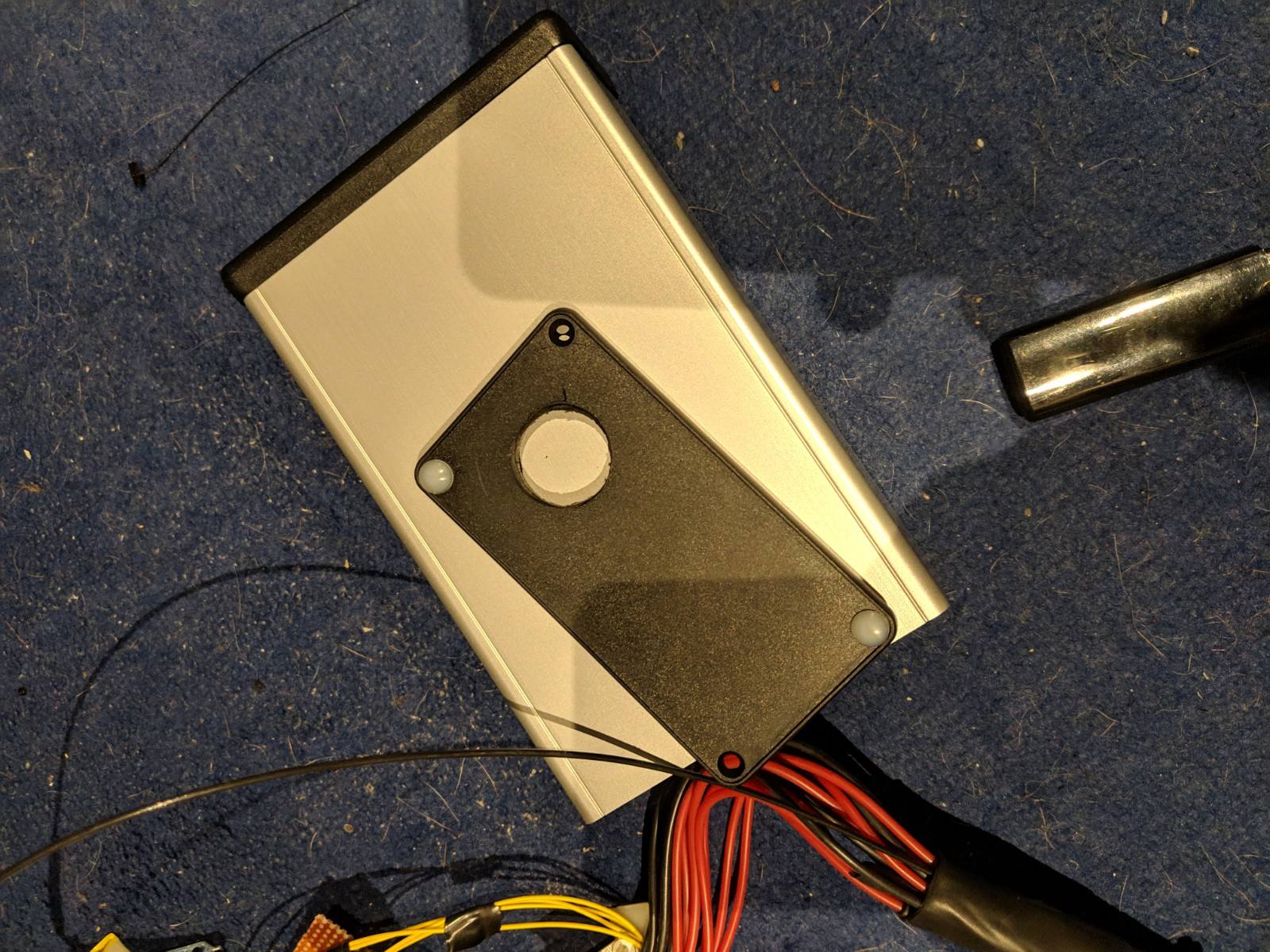
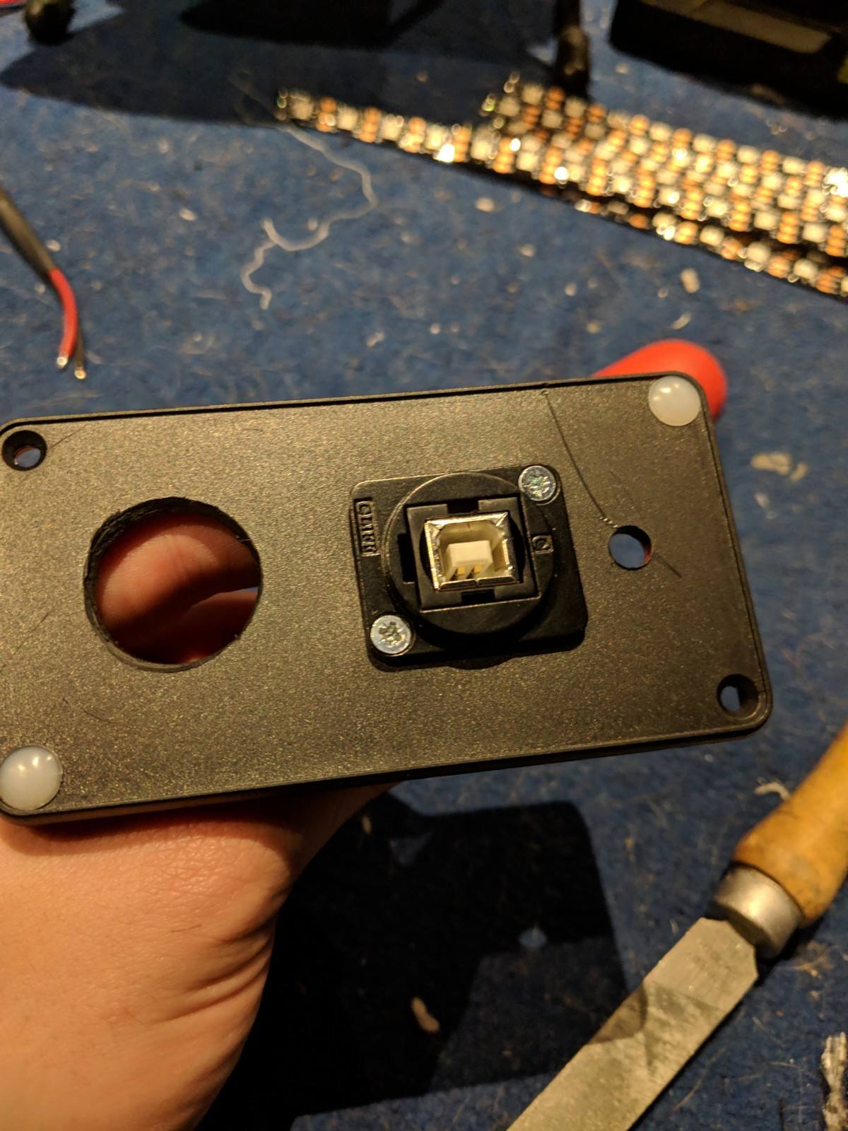
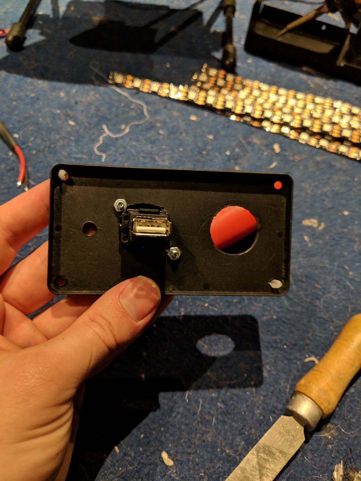
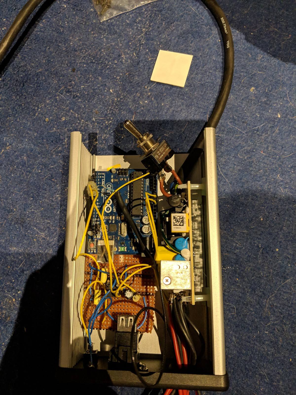
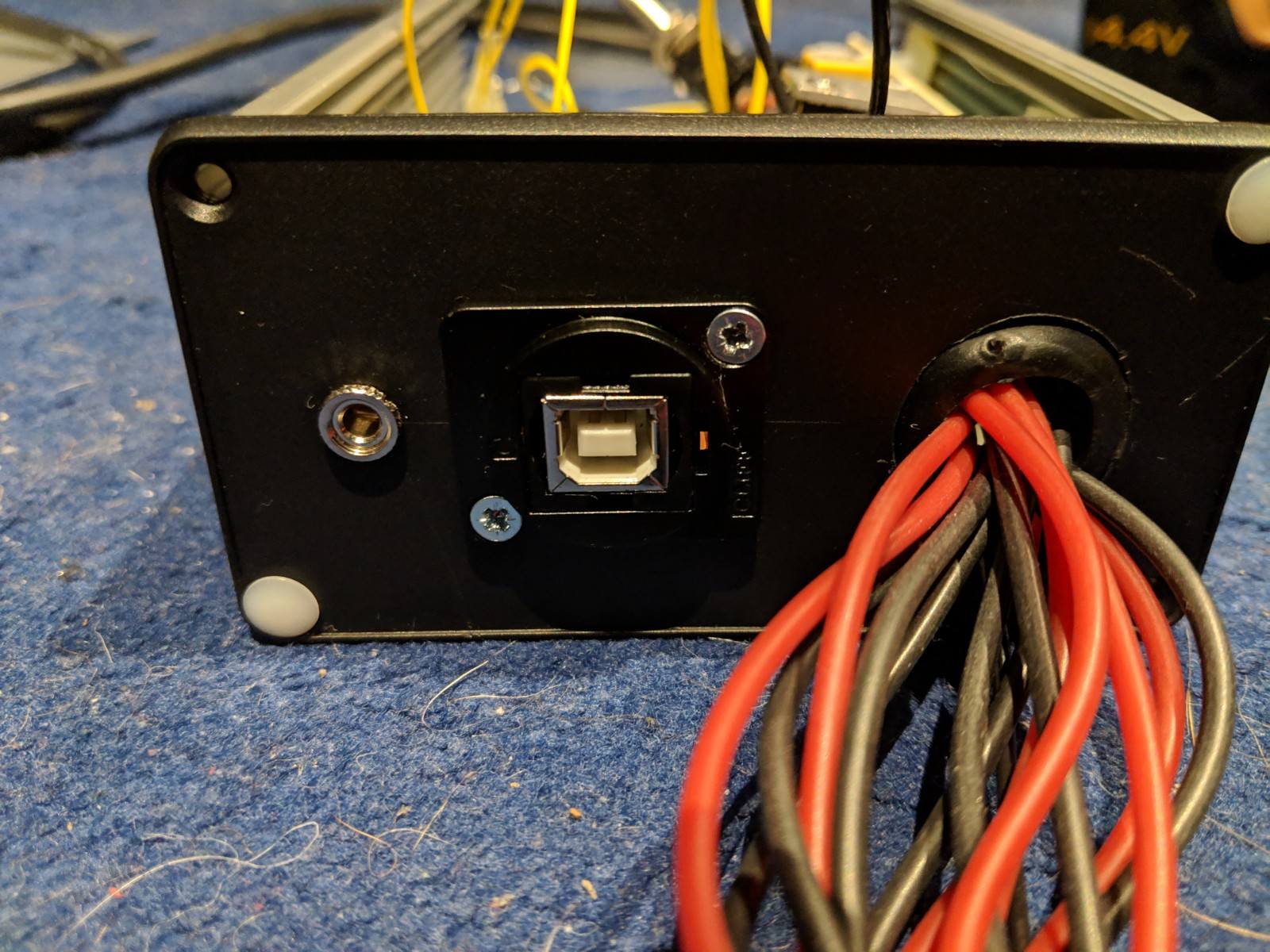
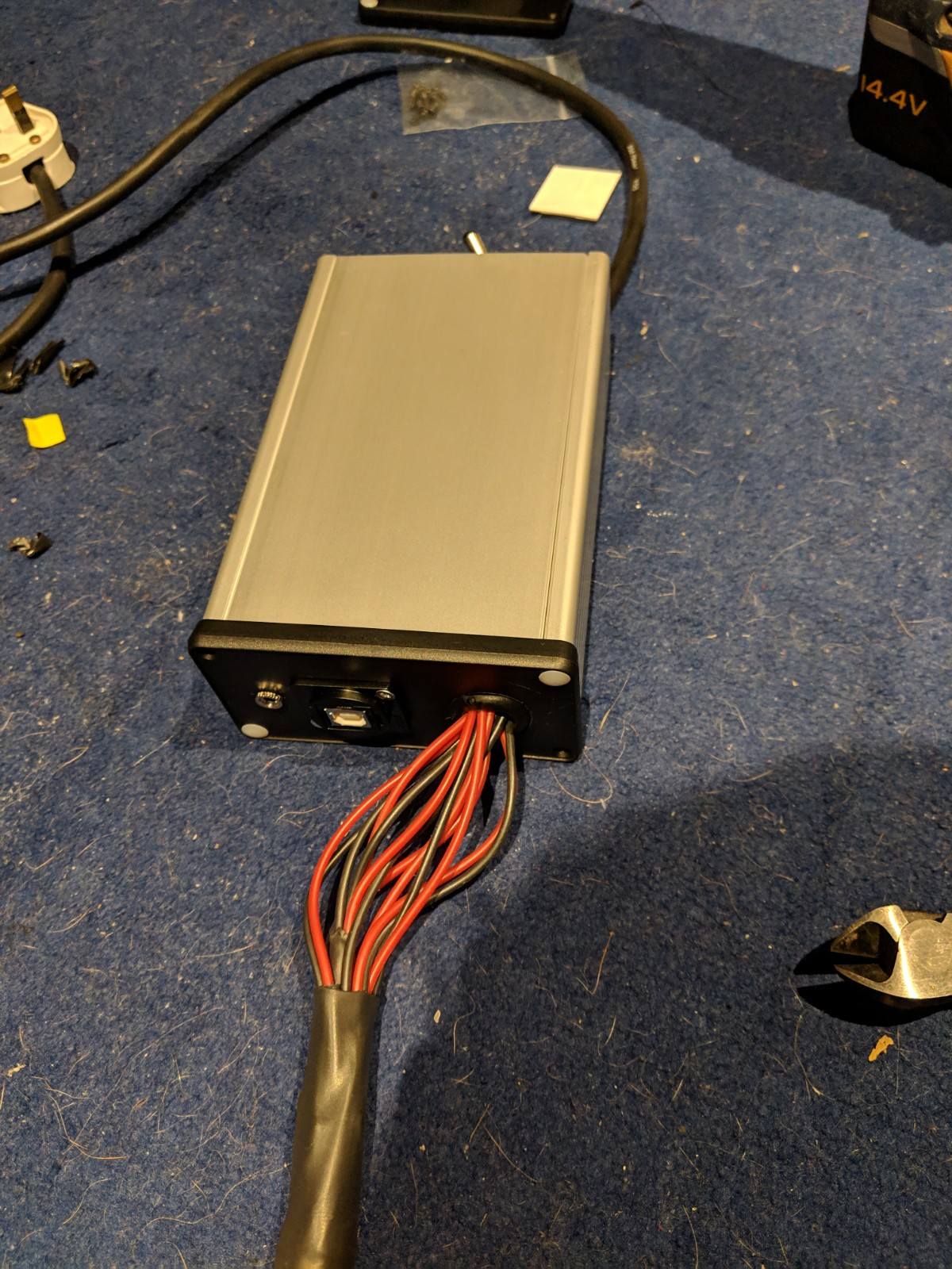
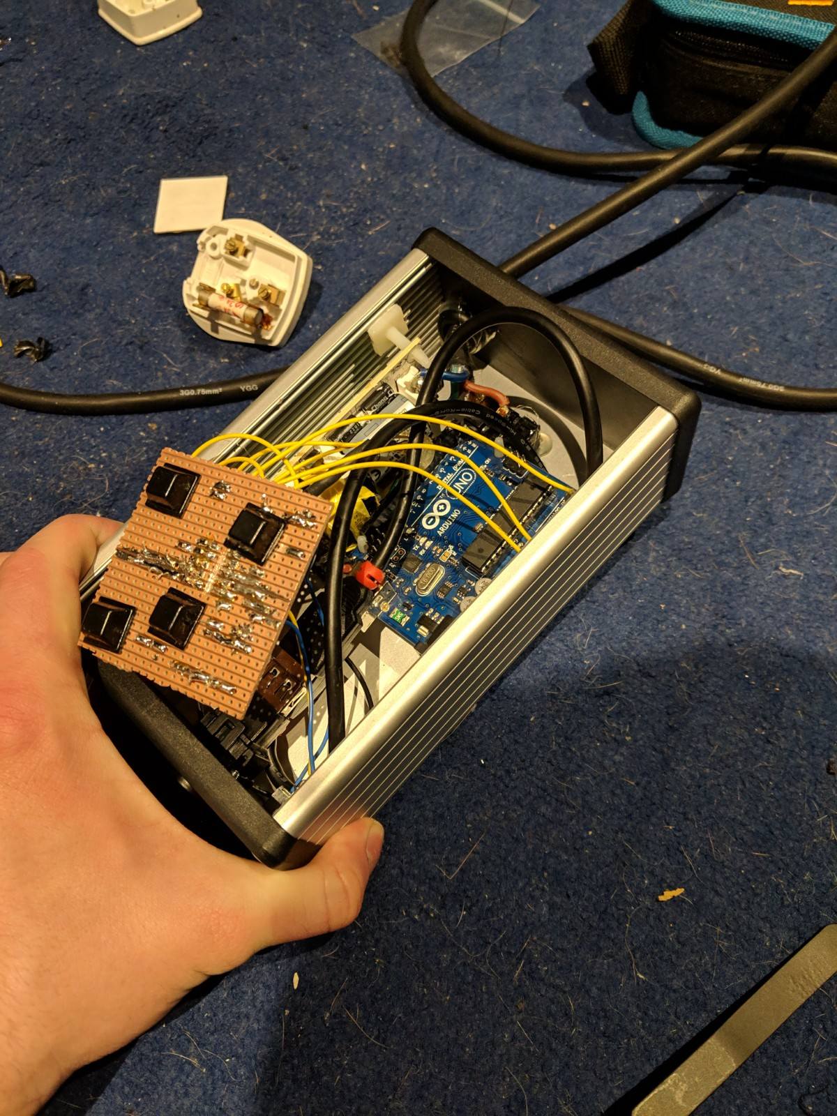
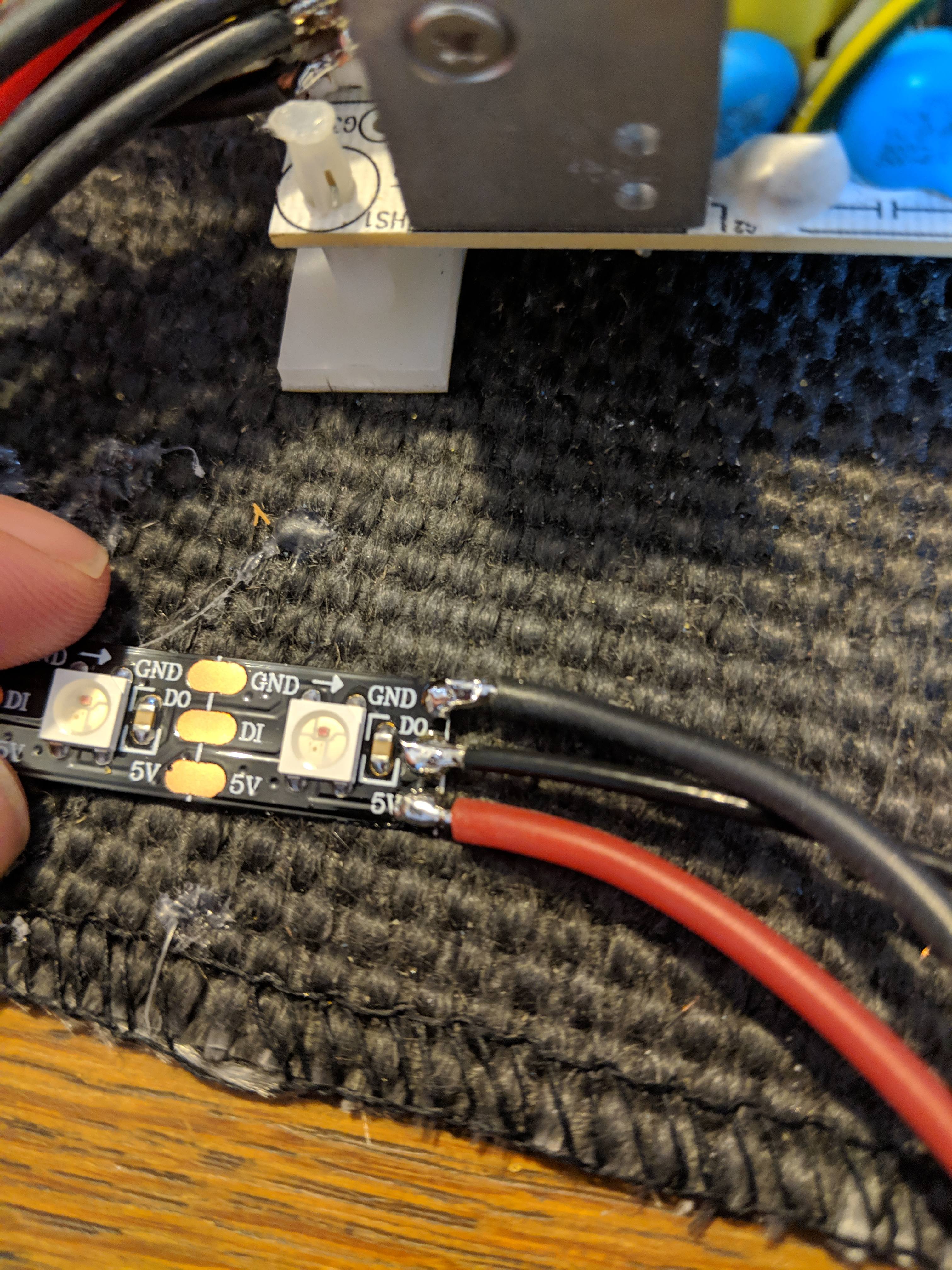
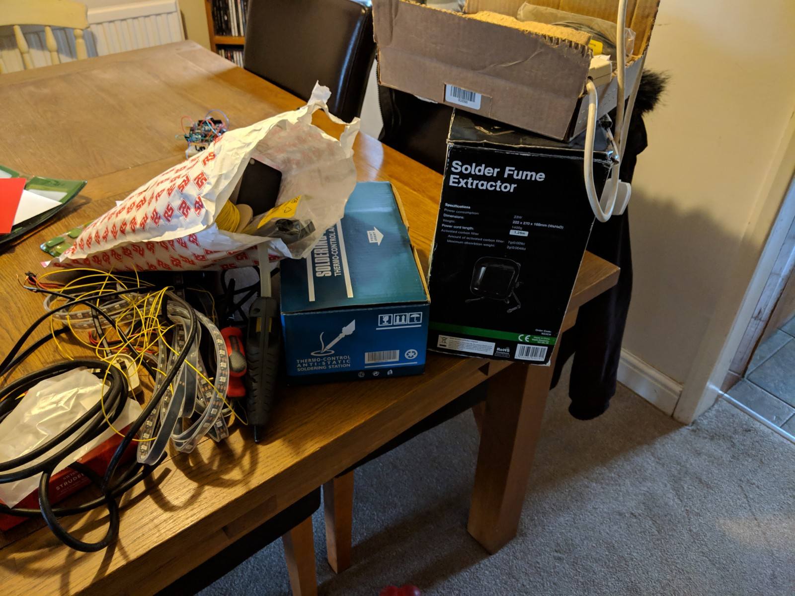
Put a good few hours into the project last night. Didn't have time to post an update here, but planning on having it finished this evening. Last night, I kind of restarted the LED part of the build, as when I tried to untangle the mess of LED strips, the data lines pulled their pads off the strip. I bought some new LEDs and the diffusers. Since the diffusers were a metre long, I made the LED strips for each band a metre long too. This means I've now got 420 LEDs (60 per band) rather than 300. The code will need a bit of adjustment to work with this. So, last night I cut the enclosure to fit the 3.5mm jack, power switch, power cord, LED wiring and USB input. I also sleeved all the LED wiring, and started mounting everything into the enclosure. All that's left to do is to mount the MSGEQ7 board in the enclosure, solder up all the LED strips, and mount them into the diffusers. I'll post a final update either tonight or tomorrow (hopefully with a video of it working!) Photos (in a random order):
-
[Finished!] Wall Scale Graphic Equaliser Build Log
rhyseyness replied to rhyseyness's topic in Hobby Electronics
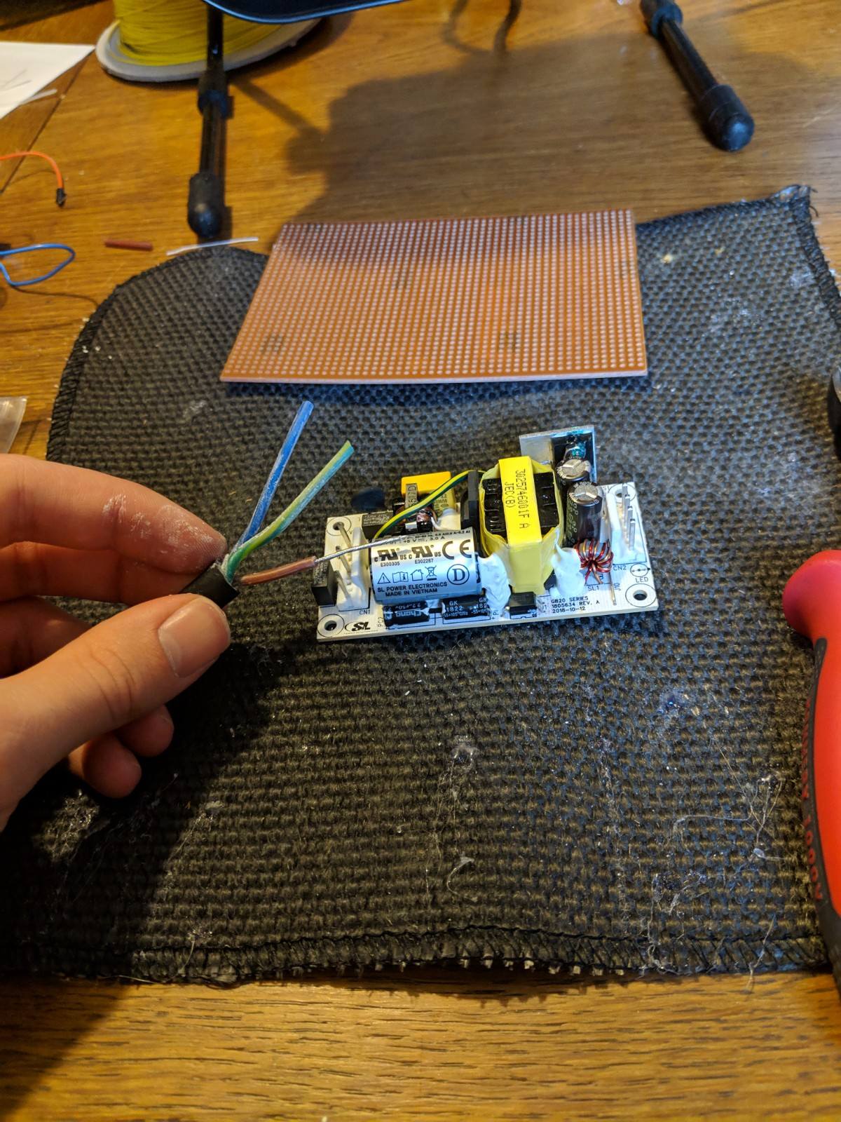
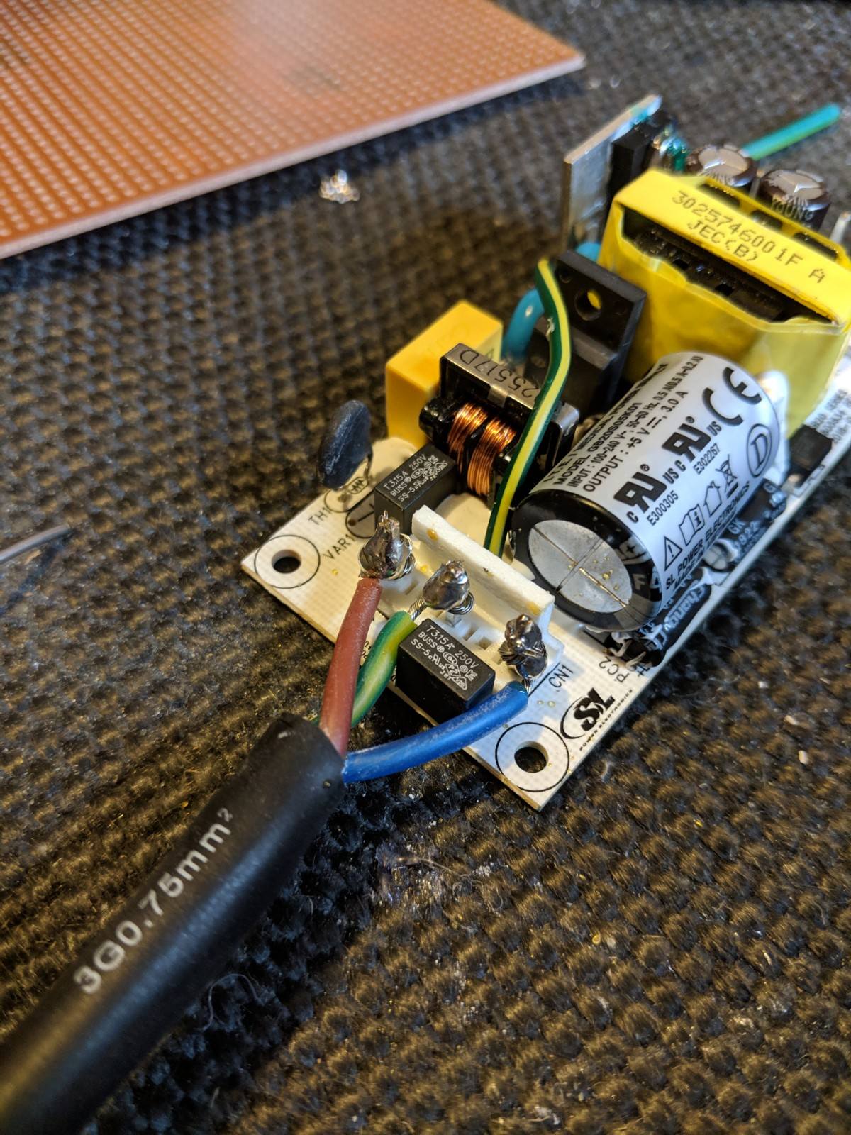
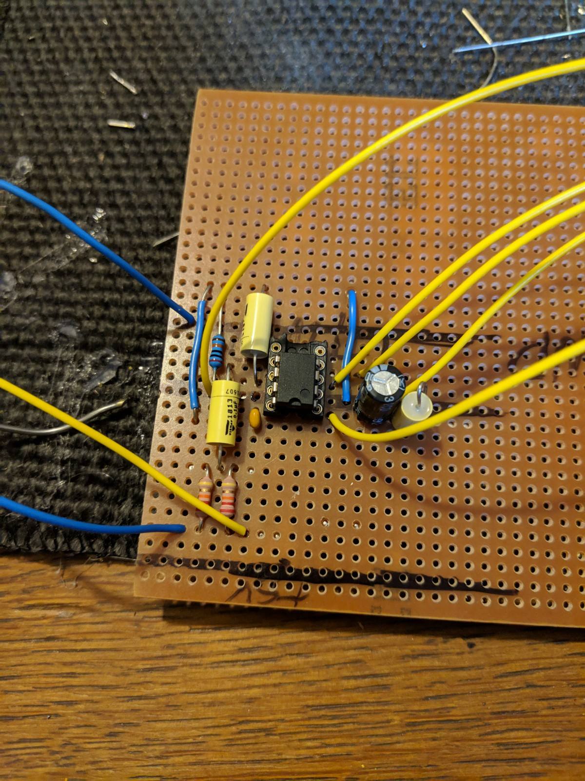
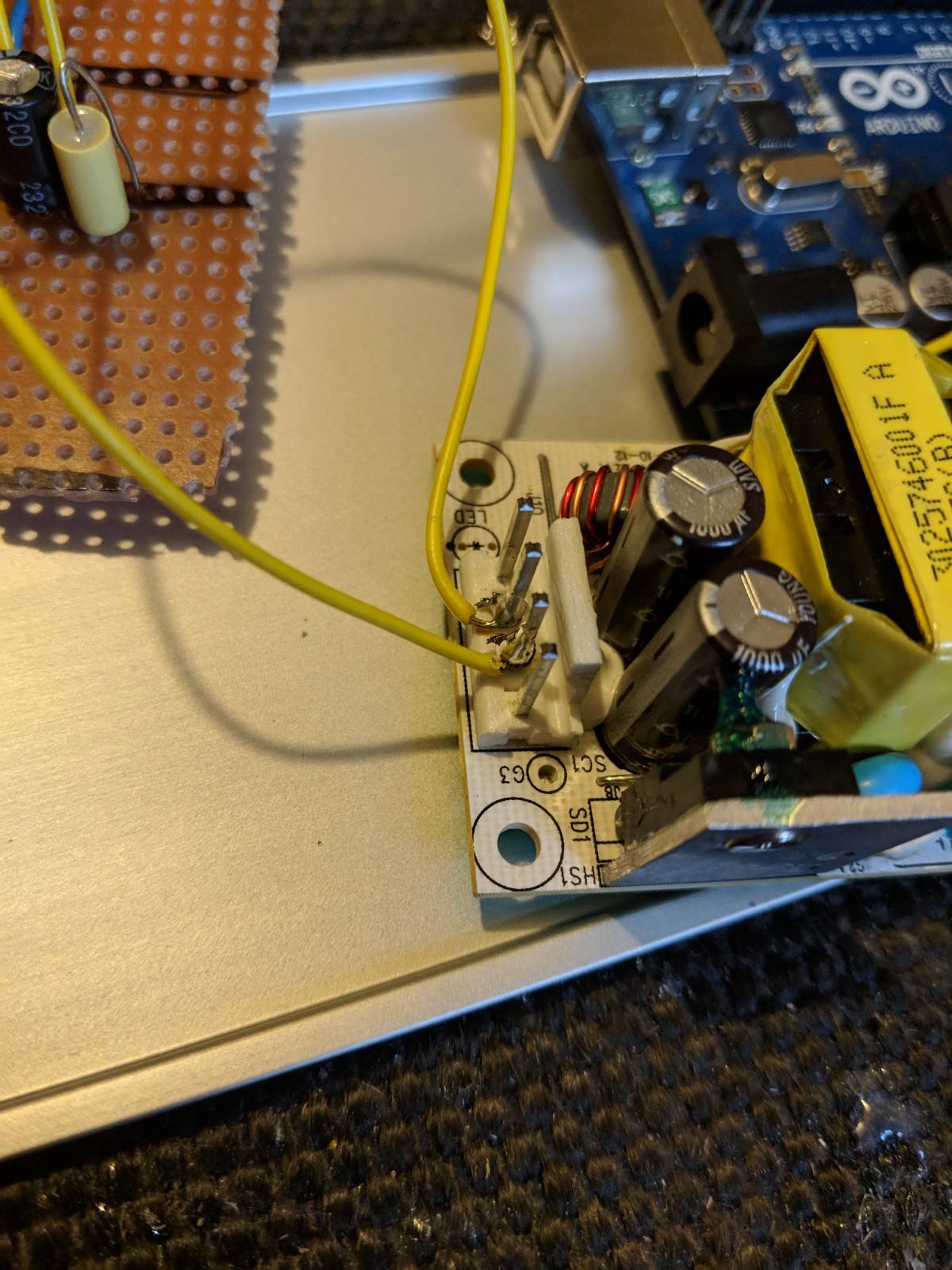
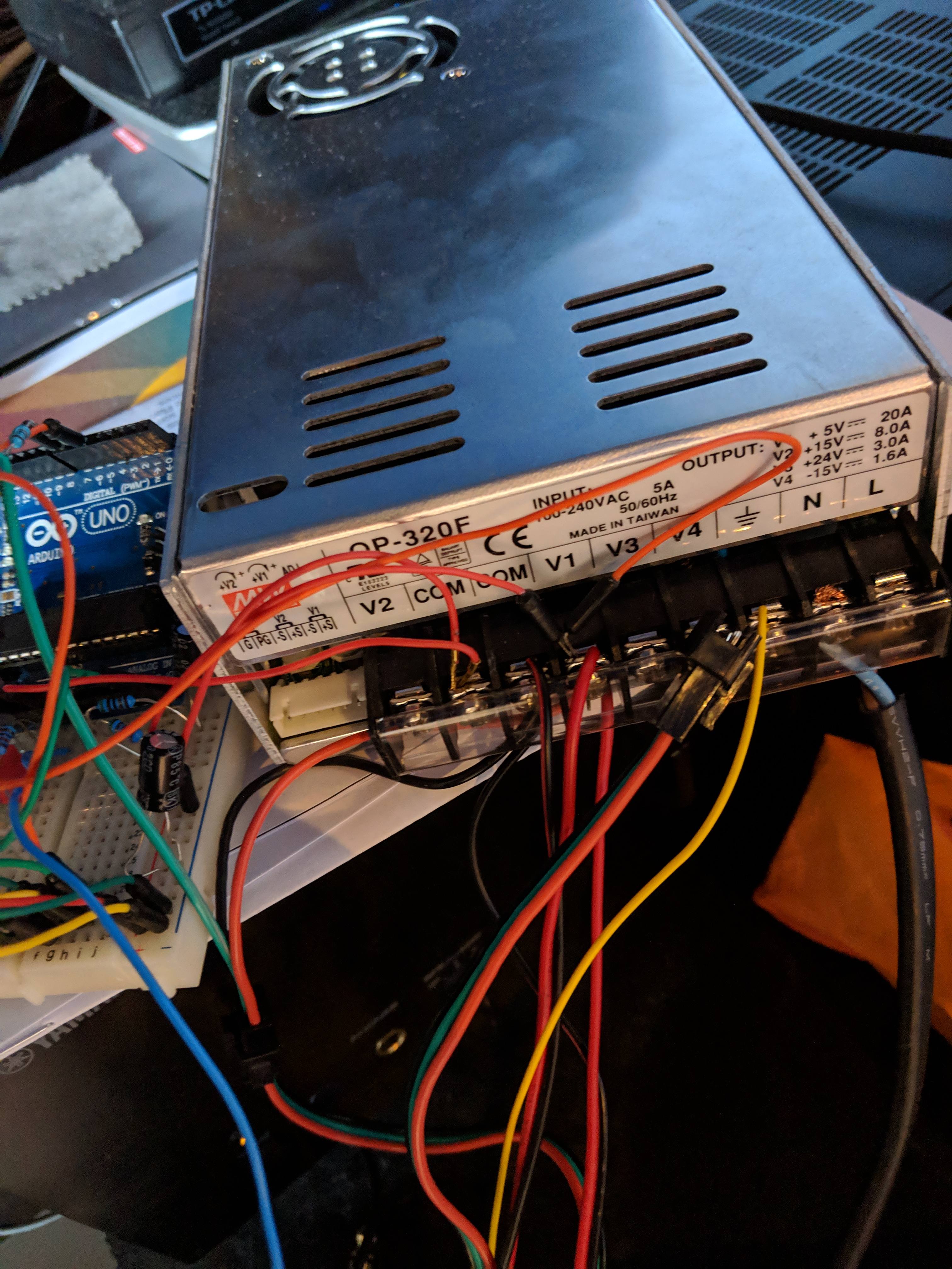
All fair comments. Cheap was the name of the game here. All your suggestions make a lot of sense. The purchasing decisions were based on what I already had laying around and how inexpensive stuff was. The 0.1uF caps were what I had around from an old project (they were used for decoupling power supplies on that). I don't have a spare wall wart adapter or barrel jack laying around, but I do have a spare mains plug and twin and earth cable, hence the straight 240V->5V PSU (which was also only £12). 15W should be plenty for the application. All my stuff was from Mouser or RS components (so a little more expensive than ebay) as I was burnt initially buying the MSGEQ7's off ebay, which all had at least one band not working. Soldering onto the regulator would have been a way better idea than hot glueing into the power headers. I might change that later, I'm hardly pulling any power through the Arduino so shouldn't have a problem at least. Stereo jack is going to be mounted on the enclosure, so did it with flying leads so I could choose where to put it on the box (who needs signal integrity anyway right?). Different colours for the data would have been handy for building, but since it's going to be mounted on my wall, and I don't think I'm going to be able to hide all the data lines, I used black to try and make them less obvious. The different type was sufficient to not get them confused! If I was building again from scratch, and money no object, I'd have definitely done the power supply in a more efficient way, and I'd probably design a proper PCB for the Atmega and MSGEQ, rather than just mounting the entire dev board in the box! Cheers for the feedback, it's very much appreciated. To be perfectly honest I didn't put nearly enough thought into the power delivery. I went for quick and easy rather than a good engineering solution (which probably would have been less expensive too)! -
[Finished!] Wall Scale Graphic Equaliser Build Log
rhyseyness replied to rhyseyness's topic in Hobby Electronics
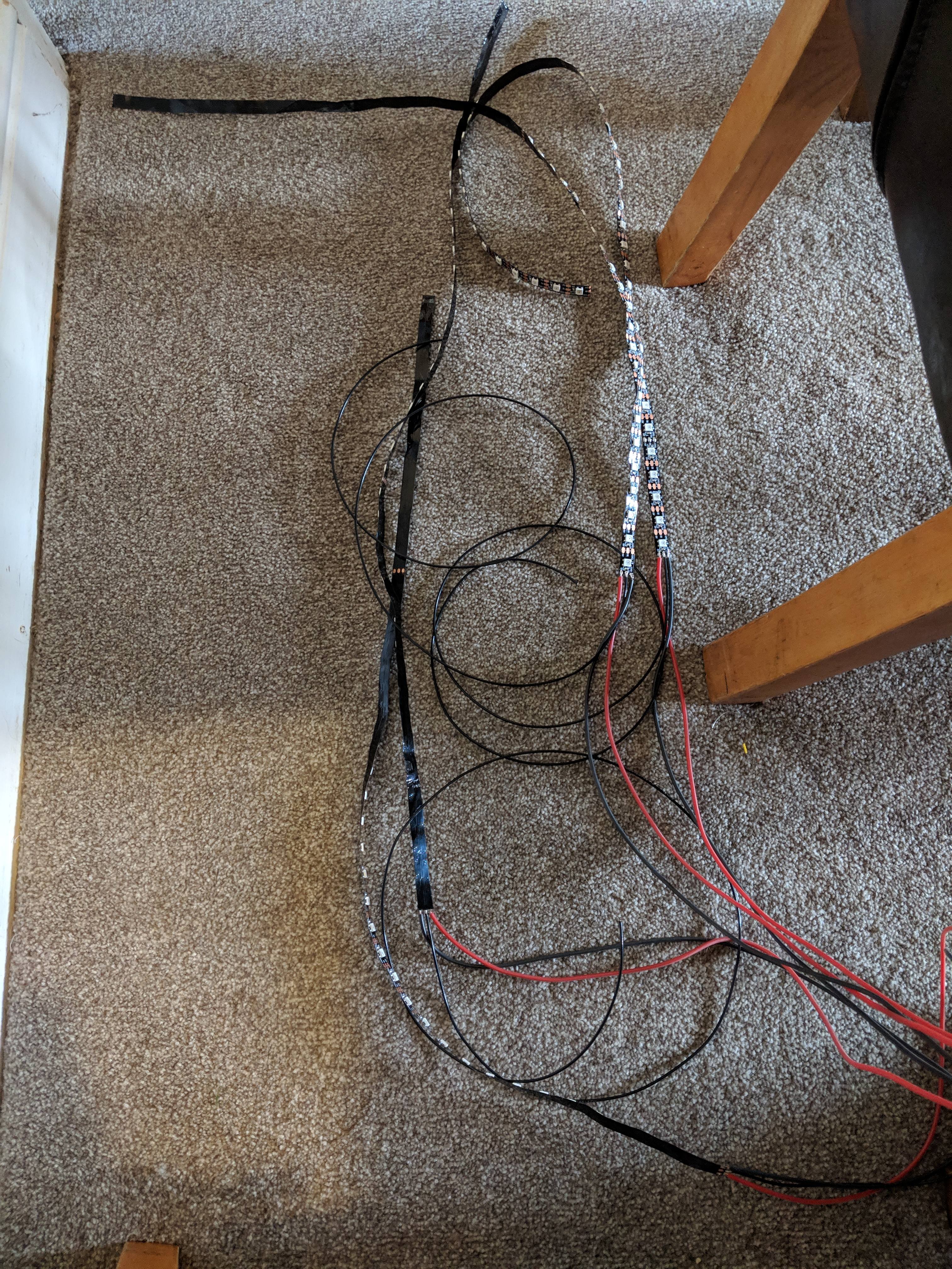
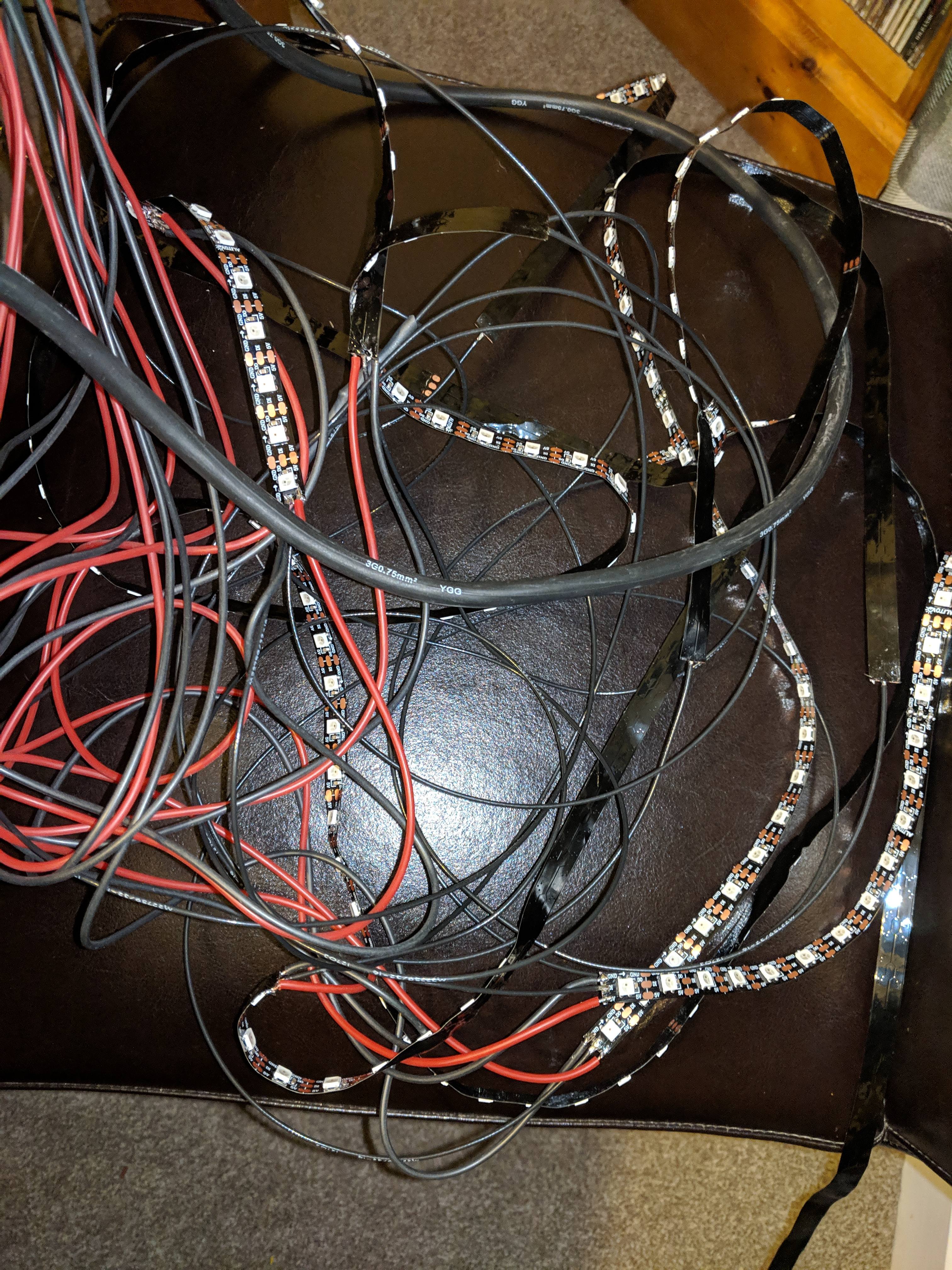
So after a little fault finding and A LOT more soldering, the electronics are up and running. All that's left now is the getting it in a box and making everything neat and tidy. The LEDs are all soldered to the power supply, each other, and broken out into 7 strips. I've ordered diffusers because the strips are super delicate now they're not in the plastic. I've tested them and they're look great. It's super messy right now. Needs untangling real bad, then can start getting bits into the box
-
[Finished!] Wall Scale Graphic Equaliser Build Log
rhyseyness replied to rhyseyness's topic in Hobby Electronics
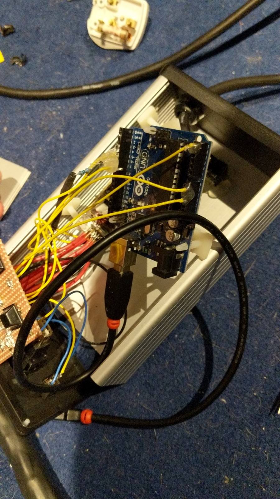
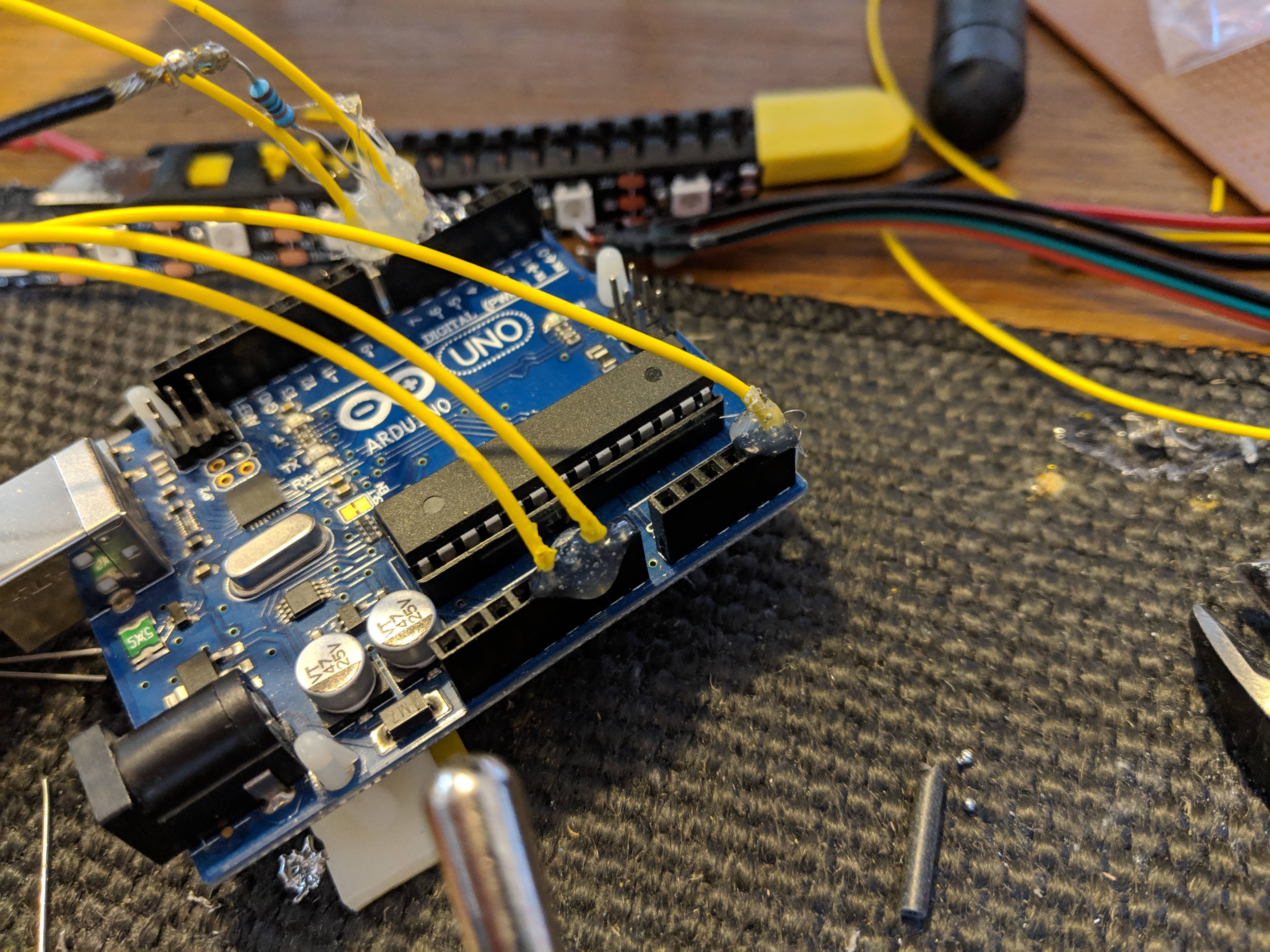
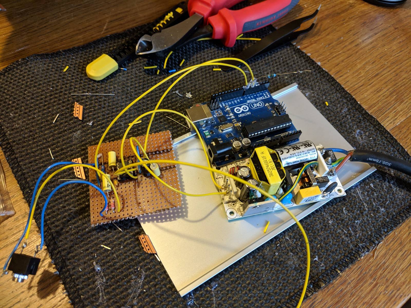
Update from yesterday afternoon's work. Started putting the system together. I've soldered the MSGEQ7 board together, and wired this into the power supply and arduino. The power supply board has had the mains power soldered on. I'll let the photos do the talking Work still remaining: Machining of the box to allow connectors and switch to be mounted. Hole to get the LED wiring out too. Power supply connections to the arduino Fitting switch to the power supply input (I'l have to de-solder what I've done already to do this. I forgot it!) Cutting LED's down to strips of 43. Connecting dataline between arduino and LED strip. Connecting power supply to each band's LED stip. Gromits fitted to cable holes on the box. Sleeving of external cables. Mount PCBs in box. Photos: Putting these photos in I've noticed a fairly big problem with the audio input. 10 internet points to anyone who notices it! More updates to come later today hopefully
-
[Finished!] Wall Scale Graphic Equaliser Build Log
rhyseyness replied to rhyseyness's topic in Hobby Electronics
Haha, thanks! The only delay should be the time for the main loop to run. I did experiment adding a delay on every main loop (see commented out delay of 50ms in "void loop"), but it just made the LEDs look weird with the audio. The only delays in there currently are the 40 microsecond ones requried for correct operation of the MSGEQ7. Everything else should be as fast as the arduino can do it! The delay of the MSGEQ7 is close to 0, but the loop certainly takes a little while to run. Initially I had the "for" loop in main go 1000 times between brightness setting, and that took about 10 seconds to update the LEDs. That suggests about 10ms per loop (input to output), and I think most of that is the FastLED library. I love the plexi glass idea- I'll have to look into the cost and how easy they'd be to wall mount without looking s***! I've got some diffusers sitting in my Amazon basket. Going to see how the LEDs look mounted bare on the wall before pulling the trigger (they're £35 for 10, which seems a little expensive to me!) -
[Finished!] Wall Scale Graphic Equaliser Build Log
rhyseyness replied to rhyseyness's topic in Hobby Electronics
I updated the code and hardware a bit today to include an ambient brightness adjustment. This uses a potential divider network with an LDR and a fixed resistor. It was a little bit jarring at first so I put some averaging in, which seems to have helped Now the LEDs brightness changes depending on the ambient brightness. Updated code below: My last few hardware bits (including a shiny new soldering iron) arrive tomorrow, so I can get on with the proper build. That's all for now. Next update is most likely to be Friday when I've got some free time after work. -
[Finished!] Wall Scale Graphic Equaliser Build Log
rhyseyness replied to rhyseyness's topic in Hobby Electronics
Yea, I've disputed it, so hopefully be back up in a couple of days. I'm going to see how it looks once it's mounted and decide if it needs any diffusion or not. Right now it is pretty eye watering, so most likely will add a diffuser! -
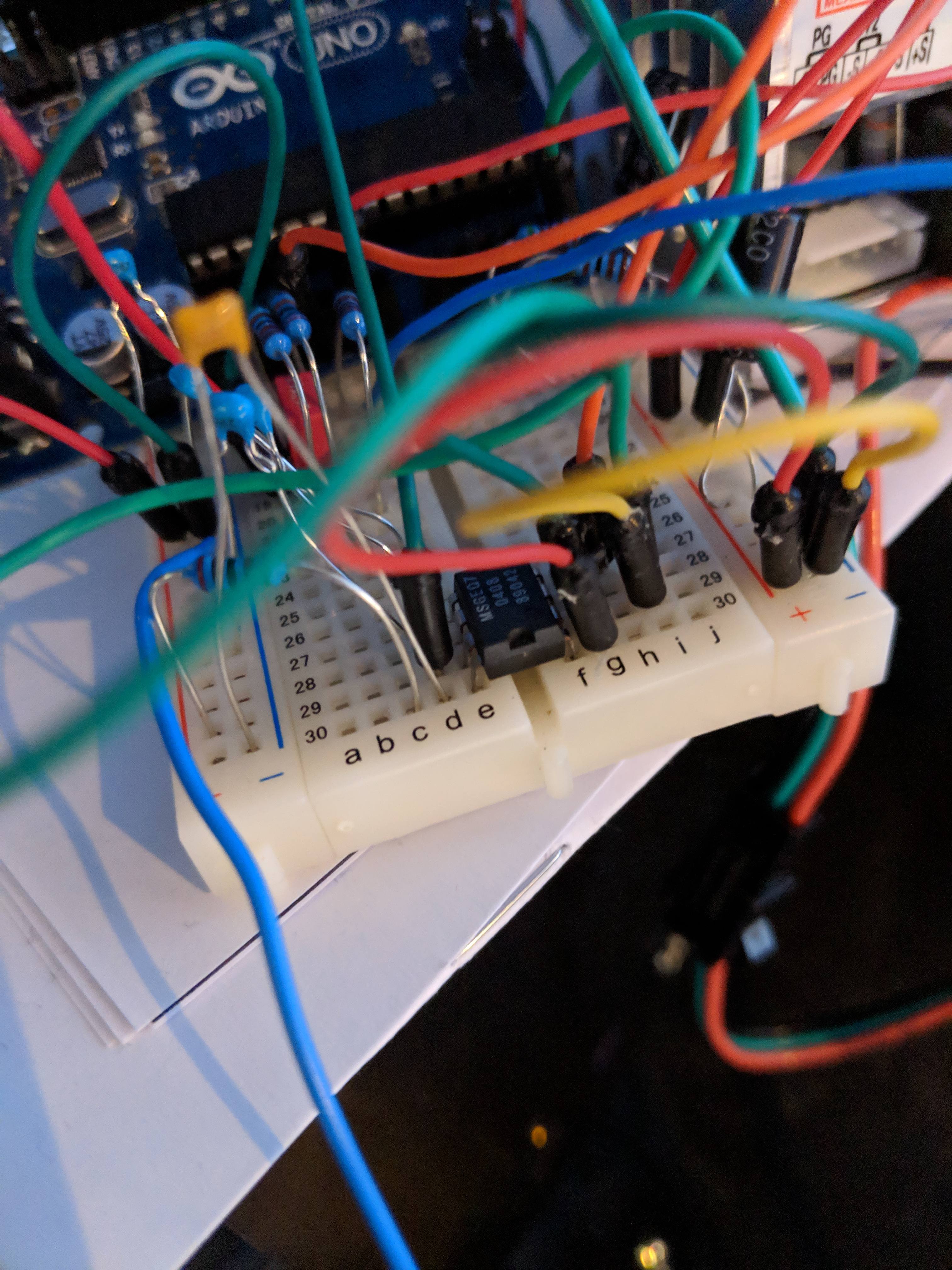
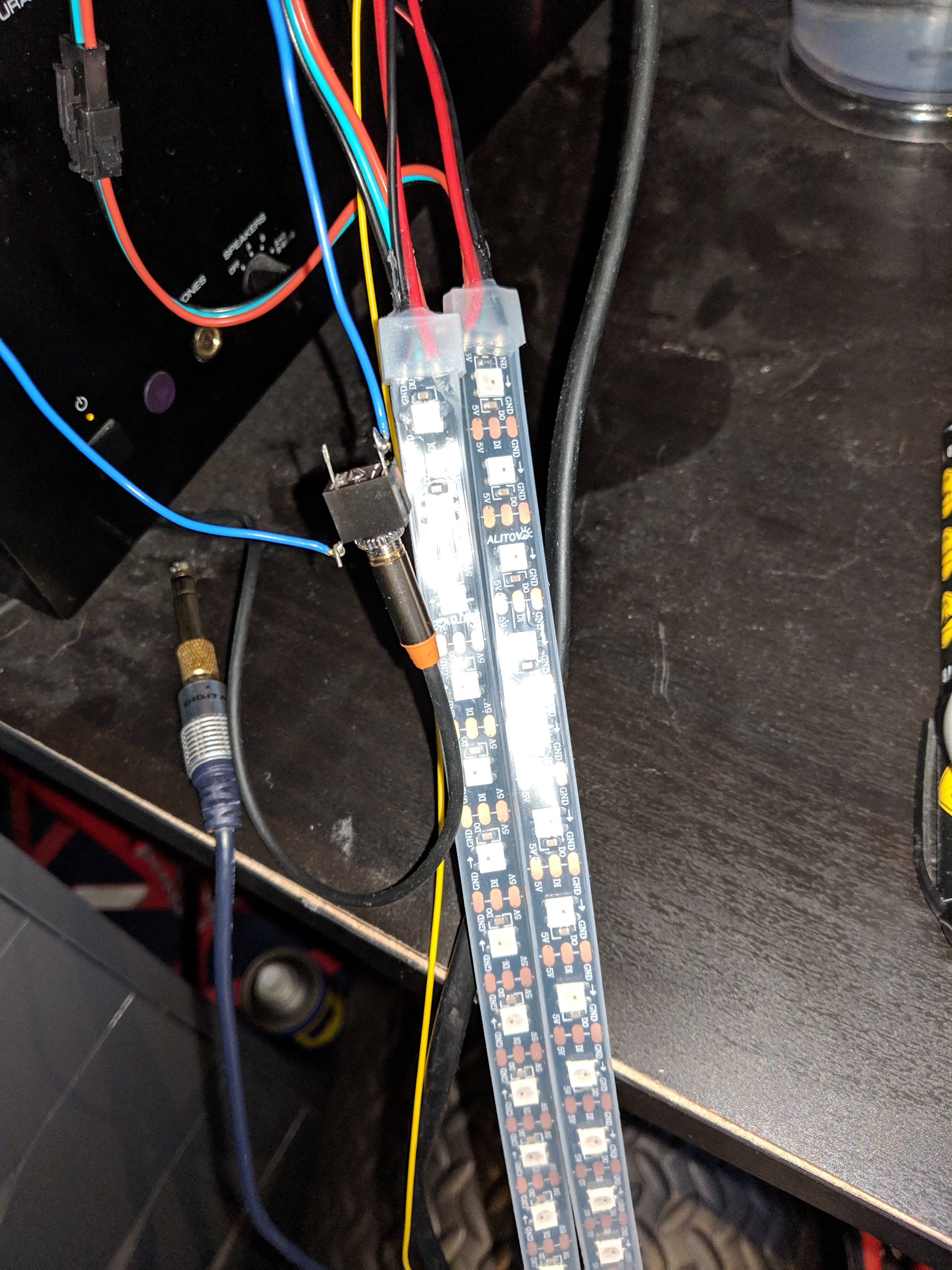
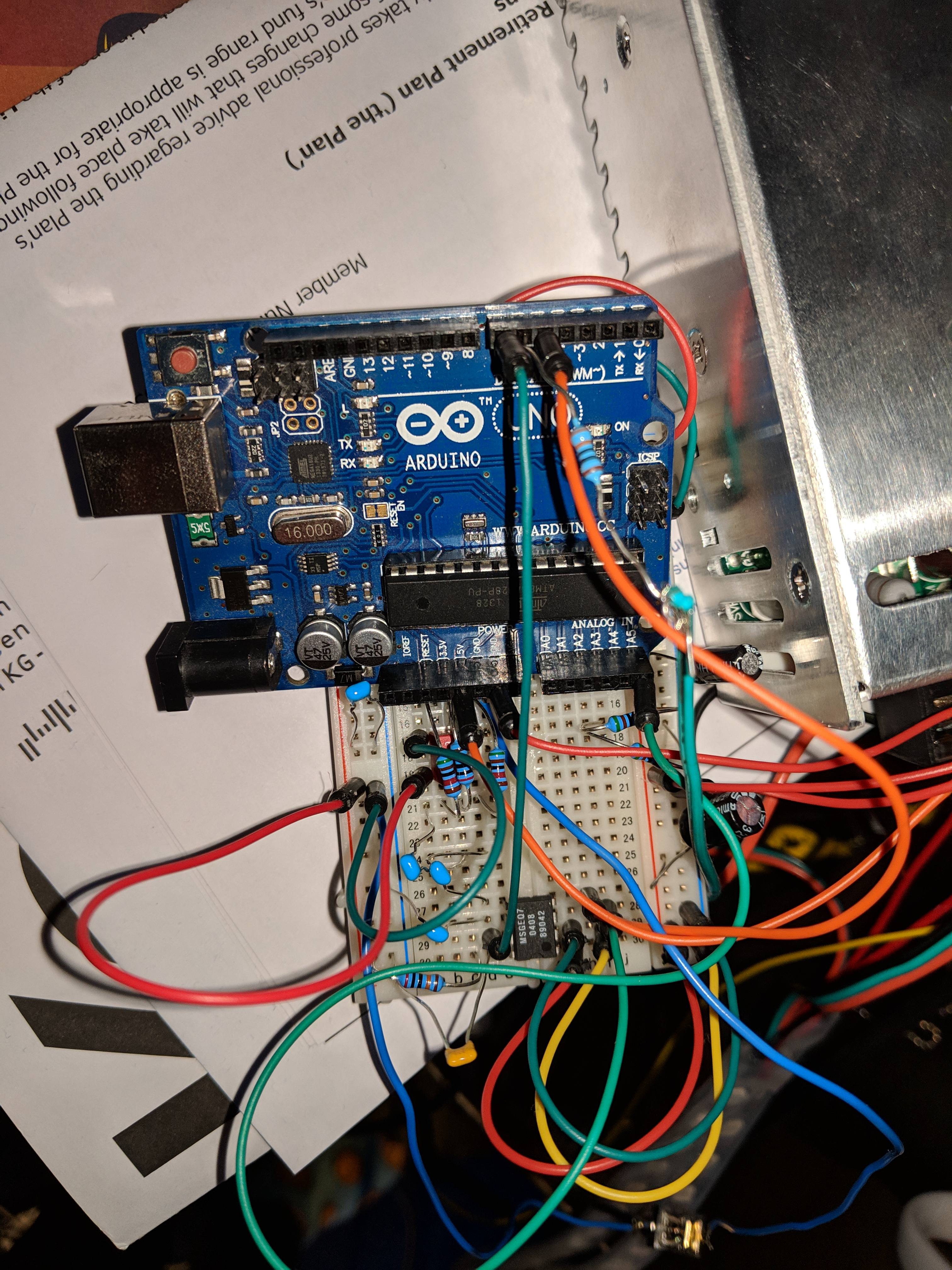
Welcome all to my graphic equaliser build log. A graphic equaliser is simply a graphic display of various frequency bands of audio. My plan is to build one from LEDs (specifically an LED strip), and mount it on my wall. I've actually done a fair bit of work on this so far, but I wanted to make sure i was going to actually finish the project before I posted about it. My plan is eventually to have this mounted on my wall. The basic operation is around the MSGEQ7 graphic equaliser chip and an Arduino Uno (Atmega 328p) microcontroller. The MSGEQ7 outputs an analogue voltage between 0 and 5V based on the amplitude of a given input within 1 of it's 7 frequency bands. The datasheet can be seen below for those of you who are interested: https://www.sparkfun.com/datasheets/Components/General/MSGEQ7.pdf I can go into more detail on this if people are interested, but I won't waste my hypothetical breath on it if no one is! This output is connected to an analogue input on the Arduino, and read by the software. The Arduino then drives serial data to the WS2812S LED strip (using the FastLED library). The LED strip is RGB and 5m long (300 LEDs). I've split this into 7 frequency bands, so each 43 LEDs represents one frequency band. The idea is that each band lights up a number of LEDs based on the volume of the sound in that frequency band (i.e. a graphic equaliser). The software is the magic part of this project, so the code can be seen below, plus some photos. The next stage is to get the hardware soldered onto strip board, and cut up the LED strip into 7 parts. I'm hoping that the code doesn't need much change from this point as I am trash at software (I'm an electronics engineer) compared to hardware. I've put up a YouTube video of it in it's current state in operation (apologies for the trash quality. It was on my phone and YouTube compression, lol). https://youtu.be/rzZRBRx6bKg Any questions, fire away! I'll post updates as regularly as I do them Code: Photos: