

The Software Enigma Machine blog Pt. 2: The Rotors

Entry posted by Mira Yurizaki
1,021 views
Part 2 in the making of the Software Enigma Machine
The Outline
A recap on the outline.
-
Part 1
- What is the Enigma Machine?
- Why did I choose to implement the Enigma machine?
-
Before Programming Begins:
- Understanding the theory of the Enigma Machine
- Finding a programming environment
-
Part 2
- Programming the features
- Rotors
- Rotor housing
-
Part 3
- Plug Board
-
Part 4
- GUI
If you'd like to look at the source code, it's uploaded on GitHub.
Programming the Features
This is where the programming magic begins, and how I went about coding each component.
The Rotors
As a recap, the physical properties of the rotors are that they have pins, in this case 26 for the letters of the alphabet, a pin on one side maps to a pin on the other, and the rotors need to be able to "advance." One thing, I didn't want the rotors to be fixed to scrambling letters. So the pin names are referred to by their number, not by any letter or other character. And to help describe the "input" or "output of the rotors, since technically both sides could be an input or an output, I refer to the "left side" or "right side" of the rotor. The right-most rotor is always rotor 1, and is the first and last rotor the signal travels through.
So this makes the pin mapping easy: it's a List of integers. A List in C# is accessed like an array, so the index of the List are the pins on the "right side", while the value of that element in the List are the pins on the "left side." So to get a right side to left side mapping:
return mapping[Pin];
However, there's a problem, how do you get the left side to right side mapping? There could be another List that contains the opposite mapping, but Lists have a method, IndexOf, that finds the first index that has a value. While this might be a problem if we had mappings to the same pin, the mapping is always 1:1 and unique, so there's no danger of using this method and have it return something that isn't actually where a pin is mapped. So getting the left to right mapping is:
return mapping.IndexOf(Pin);
That takes care of the basic aspect of the rotors. But they still have to "advance" or have an offset such that the same letter gets a different pin each time its selected. Also, each rotor has to have a different offset, since they don't advance at the same time. At first I tried doing some math with the Pin and adding an offset, but nothing lined up. And to make matters worse, I started with four rotors and I wasn't even sure if the rotors were working. So this confused the heck out of me when it was wrong and I couldn't figure out why. So instead I opted for the rotors to create a temporary list that copies entries from the original but at an offset.
private List<int> getOffsetList() {
  List<int> tempList = new List<int>();

  for(int i = 0; i < mapping.Count; i++)
  {
    int position = (i + pinOffset) % maxPins;
    tempList.Add(mapping[position]);
  }

  return tempList;
}
This worked, so I continued work from there. However I wasn't quite satisfied with this solution. While my initial check-in of the code has this, I went back to change how the mapping with the offset is obtained. But since this method works, I used this as a reference point to develop the new one using what pin is used as the input and what the current offset is. The result is:
public int GetPin_RtoL(int Pin)
{
  Pin = Pin + pinOffset;
  Pin = Pin % maxPins;
  return mapping[Pin];
}

public int GetPin_LtoR(int Pin)
{
  Pin = mapping.IndexOf(Pin) + (maxPins - pinOffset);
  Pin = Pin % maxPins;
  return Pin;
}
So to explain how this works:
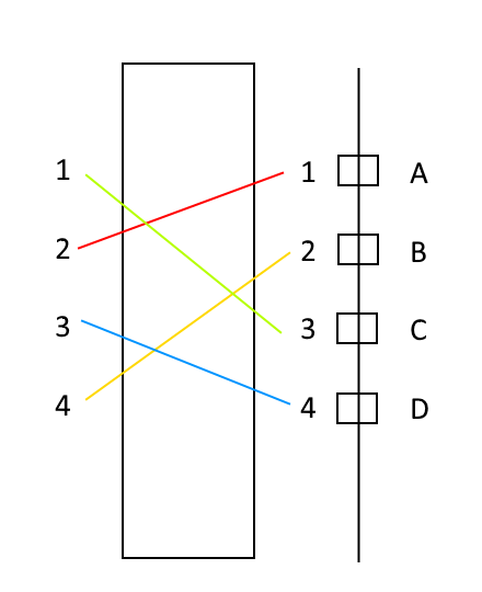
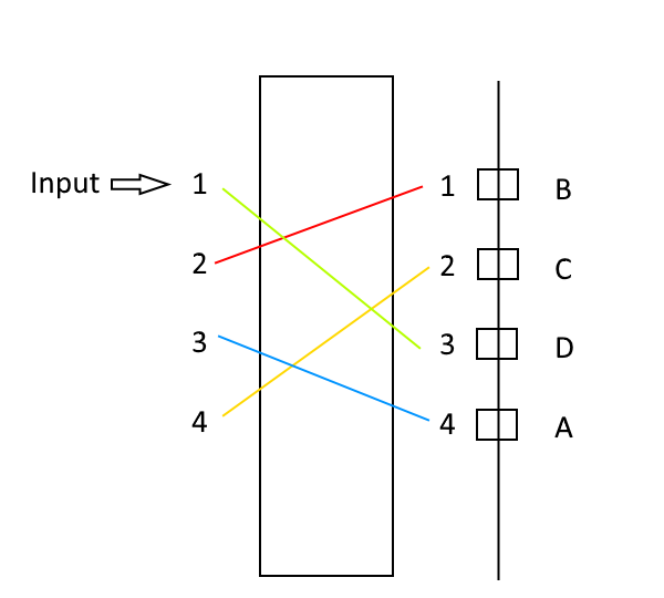
Let's look at this rotor. The input is pin A, which is connected to rotor pin L-1. The output doesn't matter, but going through the loop, the rotor advances and becomes this:
Pin A is now connected to rotor pin R-2, which will output Pin L-4. But from the perspective of the rotor, it really looks like this:
So to account for this, the rotor offset is added to the input pin. Since Pin A would've connected to rotor pin R-1, adding the offset (1 position in this case) and doing a modulo operation makes Pin A map to rotor pin R-2.
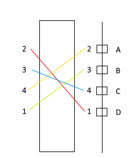
Now, what about from the left to right mapping? To start, let's say the rotor has advanced three positions:
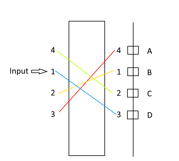
The input is coming into pin L-1 which maps to pin R-3. But from the rotor's perspective it's:
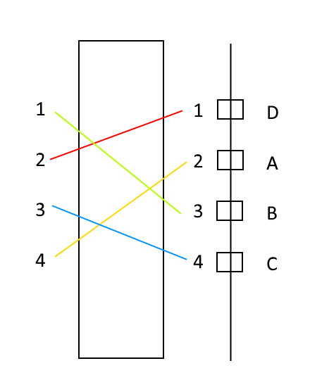
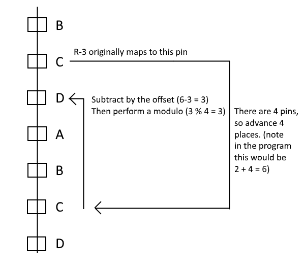
The problem is that the IndexOf method will return Pin R-3. If taken at face value, the app will think R-3 is the real output, which in the non-offset way maps to pin C (confused yet?). So we have to take the output pin value and modify it so the app believes the correct ABCD pin was outputted (in this case Pin D). To modify this, take the reverse mapping as normal, add how many pins there are on the rotor, then subtract the offset. Then, take that value and perform a modulo by the number of pins to get the correct mapping.
EDIT: Realizing how confusing that explanation is, here's a diagram to visualize how to get the answer:
With the main logic out of the way, all that's left is to get what the current position (or offset) the rotor is in and a way to set it. Those are straight forward and easy.
The Rotor Housing
The rotor housing, for lack of a better name, contains all of the rotors and handles the interface between the rest of the system and the rotors themselves. These interfaces are:
- The key press scrambler
- What position the rotors are in
- Set the position of the rotors
The constructor for this class can set an arbitrary number of rotors, how many pins they have, the random seed to use (this is to control the RNG), and a List that maps what "key" is tied to which pin. The mapping is used to translate a string character to a number since the rotor class uses a number. The number the rotor spits out is used to figure out which character to use as the encoded text.
There are two private methods to run the key input through the rotors and another to advance the rotors. In either case, since the rotors are in a List and a List can be accessed like an array, a first cut approach could be to use a for-loop to loop through each rotor. So the code would've been something like this:
string output = "";

for (int i = 0; i < InputText.Length; i++)
{
  string letter = InputText[i].ToString();
  int inputPin = charMapping.IndexOf(letter);
  int outputPin = rotors[rotor].GetPin_RtoL(InputPin);;

  if (inputPin > -1){
    for (int rotor = 1; i < rotors.Count; rotor++){
      outputPin = rotors[rotor].GetPin_RtoL(outputPin);
    }

    /* Reflector rotor */
    outputPin = rotors[rotor].GetPin_RtoL(outputPin);

    for (int rotor = rotors.Count; i >= 0 ; rotor--){
      outputPin = rotors[rotor].GetPin_LtoR(outputPin);
    }

    output += charMapping[outputPin];
  }
  else {
    output += letter;
  }
}
Seems simple enough, but I didn't want o take this approach. If only because I didn't like the multiple for-loop usage. So instead I decided upon a recursive method that looks like:
private int getRotorOutput(int InputPin, int RotorNum)
{
  int outputPin = 0;
  if(RotorNum < rotors.Length - 1)
  {
    outputPin = getRotorOutput(rotors[RotorNum].GetPin_RtoL(InputPin), (RotorNum + 1));
    outputPin = rotors[RotorNum].GetPin_LtoR(outputPin);
  }
  else
  {
    outputPin = rotors[RotorNum].GetPin_LtoR(InputPin);
  }
  return outputPin;
}
The method takes in an input pin and which rotor to start on. If the rotor number isn't the reflector (noted by being the "last rotor"), it calls the function again. However the input that gets fed is the output of the rotor mapping (going right to left). When the reflector is hit, it doesn't call the method again, and so it returns the output. When the method returns with the right side pin being used of the last rotor, gets the left to right mapping, and returns that.
Admittedly, the for-loops method is easier to understand, but I wanted to use a recursive function for this on the idea that the rotor count is arbitrary and having multiple loops didn't sound appealing. A similar thought process was done with the rotor advancing method. To advance each rotor properly (the right side advances every time, the next one advances when the right side makes a full cycle, the next one advances when the previous one makes a full cycle, etc.), a straightforward approach would be to do something like:
bool advanced = false;
rotors[0].advanceRotor();
if(rotors[0].GetPosition() == 0)
  advanced = true;

for(int i = 1; i < rotors.Count; i++);
  if(advanced == true){
    rotors[i].AdvanceRotor();
    if(rotors[0].GetPosition() == 0)
      advanced = true;
  }
  else
    break;
}
The recursive method is:
private void advanceRotor(int RotorNum)
{
  if (RotorNum == rotors.Length - 1)
    return;

  rotors[RotorNum].AdvanceRotor();
  if (rotors[RotorNum].GetPosition() == 0 &&
      RotorNum < (rotors.Length-1))
  {
    RotorNum++;
    advanceRotor(RotorNum);
  }
}
Which again, while the for-loop method is easier to read, it also feels a little more complicated. Part of the problem is that, aside from the rightmost one, the other rotors only advance when the previous one made a full revolution. So the for-loop method has checking to see if the rotors made a revolution, and if it did, mark a flag so it can advance the next one. The recursive method doesn't need the flag.
There is a flaw with the recursive method, like most other recursion methods: if there are too many rotors, the stack could blow up. But given the small amount of rotors likely used for this code, the chances of it happening are limited. Unless you really want a 1000 rotor Enigma Machine. Even then I don't think the stack would blow up unless you want a stupid number of rotors.
0 Comments
There are no comments to display.