Jump to content

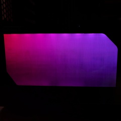
DIY RGBW Power Supply Shroud

Hello,


Here I will show you how I built my power supply shroud with beautiful RGBW lighting as seen in the pictures below.


As I do not have a RGBW header on my motherboard i will control the LEDs using an Arduino Nano (instructions in the end).


Amount of work: 2 hours (if you are fast).


IMG_20170612_214737-01.jpeg


PARTS

  • Acrylic glass (or similar). I used 4 mm or 0.157 inches thick.
  • LED strip, 60 LEDs/meter. Bought 1 meter (3.3 feet) RGBW LED strip from eBay for $8.30. Note that RGB led strips are significantly cheaper than RGBW led strips and none addressable leds are cheaper than addressable ones.
  • Double sided tape. 
  • Arduino Nano (optional), bought from eBay for $5.10.


BUILDING THE SUPER AWESOME RGBW SHROUD

Take a look at the pictures of my shroud before beginning. Picture your own finished shroud in your own case so that you get an idea of the placement and measurements of the shroud. I am using the Phanteks Enthoo Evolv mATX Tempered Glass case.


Step 1 - Measuring the shroud.

Remove the power supply to get access to the gap or hole you want to cover. Measure the shroud a bit larger than the hole. The extra edges allow us to attach the shroud with double sided tape and potentially rough edges will also be hidden.


Step 2 - Cutting the acrylic glass.

Cut the acrylic with whatever saw you have at hand. If you do not have a saw do not worry. With the tip of a knife you can scrape a deep and straight groove into the acrylic. Then, break off the acrylic along the groove by bending it over the edge of a table (might require some force).


Step 3 - Sanding the acrylic glass.

Sand the side that will not be seen with rough sandpaper as we prefer diffusion properties rather than pretty looks, I used 120 grit. Give the acrylic a good sanding. You want to end up with sanding marks going in two or more different directions to ensure that the light gets properly diffused. I made horizontal and vertical sanding marks.

The visible side of the acrylic shroud you want to sand with fine sandpaper, I used 400 grit. Sand only in the direction that is perpendicular to the direction to the light source (that is, parallell to the led strip).

You can experiment with different patterns but these patterns will at least look good.


Step 4 - Washing the acrylic glass.

Wash off all the dust with soap and water.


Step 5 - Installing the acrylic glass shroud.

Attach the acrylic glass shroud to your case with small pieces of double sided tape.


Step 6 - Measuring LED strip.

Cut the LED strip a little longer than the hole you are covering with the acrylic shroud. This will ensure even lighting.


Step 7 - LED strip connector.

If your LED strip does not have the necessary connectors you need to solder them on.


Step 8 - Testing the LED strip.

Test the LED strip before installing it! 


Step 9 - Installing the LED strip.

Install the LED strip so that the LEDs are hidden. This will ensure that you can not see bright spots where the LEDs are located.

For example: If you install the shroud vertically at the bottom of the case (as I did) you want the LED strip at the top of the acrylic shroud shining downward as you will be looking at the shroud from slightly above.

Also, you want to install the led strip slightly off the side of the shroud. This way the LEDs will light up the acrylic shroud from a little further distance and will help eliminate bright spots near the LEDs.


DONE!


Nice work!

Enjoy your awesome RGBW or RGB shroud!


PICTURES

Sanding_and_installation.jpg

The installed and sanded acrylic shroud seen from the inside. The cross pattern i sanded is clearly visible from the inside.


IMG_20170612_214242-01.jpeg


IMG_20170612_214123-01.jpeg


IMG_20170612_214030-01.jpeg

With RGBW leds the white is pure white.


IMG_20170612_214055-01.jpeg


IMG_20170612_214047-01.jpeg


IMG_20170612_214033-01.jpeg


***EXTRAS***


*HOW TO ARDUINO*

The easiest way to rgb things is to use individually addressable LEDs and an Arduino. The led strips from eBay are actually very good. This way you do not need to connect any transistors to the LED strip for power management as you would need to do with non addressable LEDs. 


  1. Connect the LED strip +5V (or +12V depending on your LED strip) to your power supplys +5V (or +12V). Connect the LED strip ground (GND) to you power supplys ground. Double check your connections!
  2. In one end of the LED strip there is a Din connection (Din = Data in). In the other end there is Dout or DO (Data out). 
  3. Connect the Din to one of the digital pins on the Arduino (connect to pin D6 if you are a complete beginner).
  4. Connect Arduinos ground to the LED strip ground!!! Otherwise the led chip and the signal may have different ground potentials (voltage) and the signal may be misinterpreted by the LED chip. This will cause wrong and flickering colours.
  5. Open the Arduino IDE > Sketch > Include Library > Manage Libraries... > Search for "neopixel" > Install "Adafruit NeoPixel".
  6. Restart the Arduino IDE.
  7. File > Examples > Adafruit NeoPixel > RGBW strandtest. (If you are using RGB LEDs run some of the examples without RGBW).


*DIFFERENT LED TYPES*

There are two major different led types: "analog" and "digital".


Digital led strips have three connectors: +voltage, ground and data. The positive voltage and ground are connected to the power supply and the data is connected to the led controller circuitry (in my case the Arduino).

Each individual led on the strip is controlled by a small chip. The led controller sends a data signal to the small chip which then adjusts the colour of the led accordingly. 


The controller is able to send a signal to any specific chip on the led strip. Therefore these kind of leds are called individually addressable leds.


Analog led strips have four connectors if they are RGB, five if they are RGBW. The connectors are: +voltage(red), +voltage(green), +voltage(blue), (+voltage(white)), ground.


When current is passed through from +voltage(green) to ground all the green leds on the strip will light up. The same goes for the other colours. Because of this the current draw may be quite high and it would easily burn delicate circuits. Therefore you need to connect a high current transistor to each colours +voltage connector and control the transistors with the led controller (for example an Arduino).


Link to comment
Share on other sites

Link to post
Share on other sites

Looks good! I will definitely be building one with my own tweeks of course.

PS. Stop using adafruit's neopixel library, its sluggish and not object oriented. Use FastLED instead. Or even better, use my take on the FastLED :P

https://github.com/FastLED/FastLED

DIY NZXT HUE+! So easy anyone could do it! (update) - Page 2 - Case Modding and Other Mods - Linus Tech Tips

Quote or tag if you want me to answer! PM me if you are in a real hurry!

Why do Java developers wear glasses? Because they can't C#!


My Machines:

The Gaming Rig:

Spoiler

-Processor: i5 6600k @4.6GHz

-Graphics: GTX1060 6GB G1 Gaming

-RAM: 2x8GB HyperX DDR4 2133MHz

-Motherboard: Asus Z170-A

-Cooler: Corsair H100i

-PSU: EVGA 650W 80+bronze

-AOC 1080p ultrawide

My good old laptop:

Spoiler

Lenovo T430

-Processor: i7 3520M

-4GB DDR3 1600MHz

-Graphics: intel iGPU :(

-Not even 1080p


Link to comment
Share on other sites

Link to post
Share on other sites

2 hours ago, dany_boy said:

Looks good! I will definitely be building one with my own tweeks of course.

PS. Stop using adafruit's neopixel library, its sluggish and not object oriented. Use FastLED instead. Or even better, use my take on the FastLED :P

https://github.com/FastLED/FastLED

DIY NZXT HUE+! So easy anyone could do it! (update) - Page 2 - Case Modding and Other Mods - Linus Tech Tips

Glad you like it! Post some pictures of your own version when it is done.


Yes, I know the NeoPixel library is not great. I am writing my own code for controlling the leds. The NeoPixel library is easy for a complete beginner to install and use to test the leds with so I therefore included it. :)

Link to comment
Share on other sites

Link to post
Share on other sites

Create an account or sign in to comment

You need to be a member in order to leave a comment

Create an account

Sign up for a new account in our community. It's easy!

Register a new account

Sign in

Already have an account? Sign in here.

Sign In Now

×