
Wire type C to type A 2.0

Go to solution
Solved by Enderman,
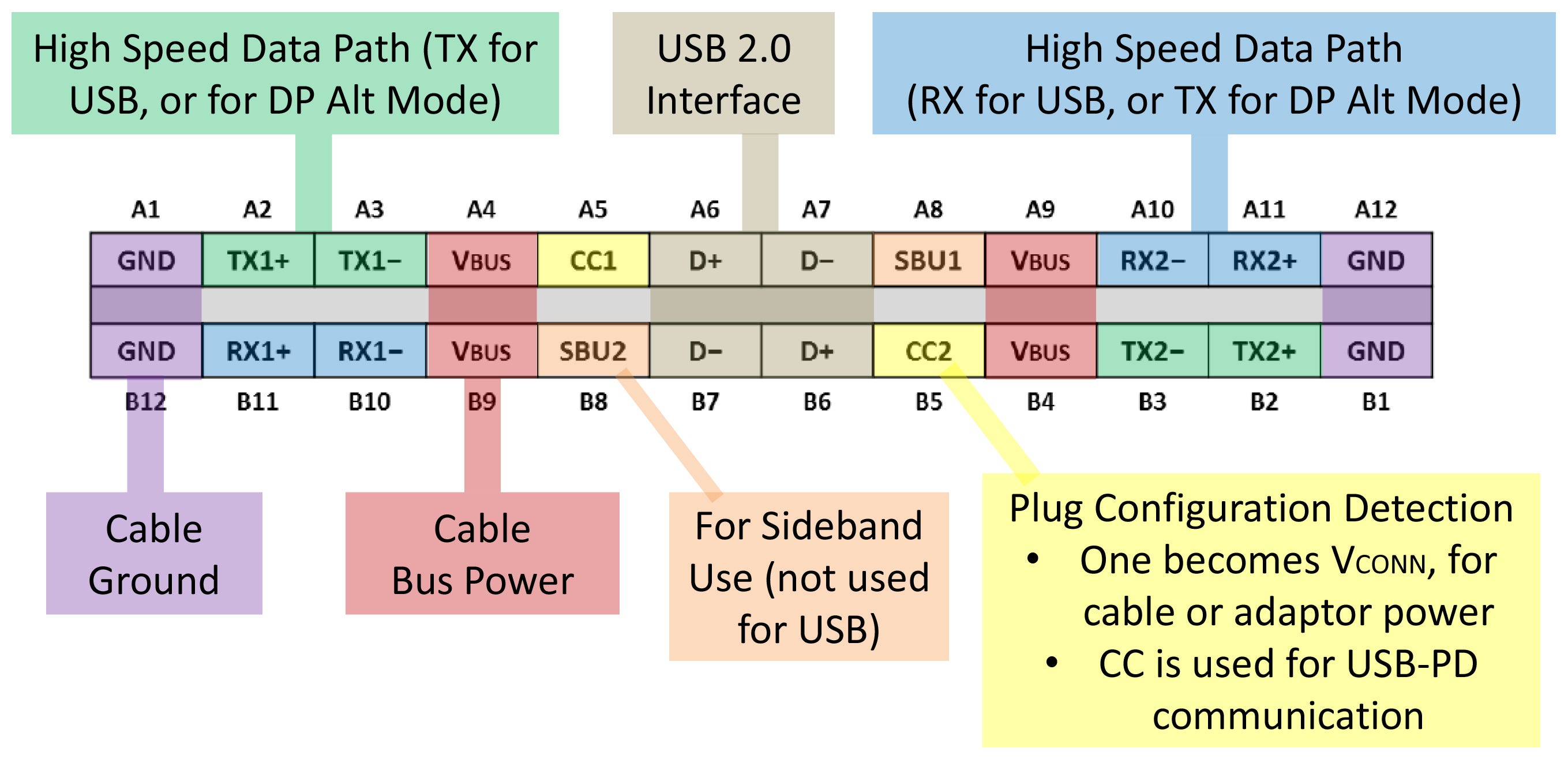
You use the USB 2.0 D+ and D- pins for data as well as the GND and Vbus for power

-
Topics
-

Tact1cal ·
Posted in CPUs, Motherboards, and Memory0 -
 3
3 -

Moosecuda ·
Posted in Troubleshooting0 -

StarsMars ·
Posted in CPUs, Motherboards, and Memory2 -
 3
3 -

ChrisLoudon ·
Posted in Cooling0 -

WolfOfValahalla ·
Posted in Graphics Cards3 -

pJay_94 ·
Posted in General Discussion11 -

tospisnot ·
Posted in Console Gaming3 -

Hellowpplz ·
Posted in New Builds and Planning5
-
-
play_circle_filled

Latest From ShortCircuit:
This wireless router can’t possibly be good… can it? - Minion Routers


Create an account or sign in to comment
You need to be a member in order to leave a comment
Create an account
Sign up for a new account in our community. It's easy!
Register a new accountSign in
Already have an account? Sign in here.
Sign In Now