Search the Community
Showing results for tags '12v'.
-
I have a Gigabyte B365 HD3 MoBo, the Thermaltake ARGB AIO Cooler I bought needs a 5v 3 pin connection for ARGB but my motherboard only has a 12v GRB connection could I buy a transfer hub that connects with SATA power and the 4 pin 12v GRB connection on my MoBo to theoretically make the Cooler actually have a working screen. And if this would work would I also be able to change the screen with the Thermaltake software.

-
hwinfo MPG A1000G PCIE5 - Low +12V value ? Should I worry ?
OrpheuS_ posted a topic in Power Supplies
Yo ! I just came across a bit of a low value for the +12V rail while under load (playing BG3) and I wanted to know if I should start to worry ? I've never seen such a low value before as they usually hover between 11.95 and 12 but rarely do they go below that. The +3.3V looks quite low as well at 3.23, never hitting the full 3.3V value. PSU : MPG A1000G PCIE5 ATX 3.0 MOBO : MSI Pro Z790-A WiFi CPU : 13700K GPU : 4090 Suprim X Any thoughts ? Let me know ! Thanks.
-
Hello guys, I'm trying to do the "opposite". I have a 12v fan with PWM and a board with a fan header of 5v+PWM. The board also has a separate 12v pin somewhere else (not a fan header and no PWM here). My idea would be to draw the power from the 12v side and the PWM+TACH from the 5v side but I'm not sure if the PWM from the 5v side would work on 12v. Can anyone confirm that? Thank you
-
 Got some bad auto settings on. Ryzenmaster when i overclocked my r5 3600 and needed to change a thing in bios. Made whole pc lag during stress test when it was normal before and got System interrupts using 5-10% CPU utilization idle and 90% usage on core 0 when it used max 1% before and even that was rare. On hwmonitor the 12v was at peak 9.8v during stress test when it read 11.9-12.1 normally before. Tested Psu wih multimeter 12v was 11.95 other voltages were good but I’m wondering if the dc/dc converters can lower the voltage? From 11.9 to 9.8? And the -12v reading was -10.8V so I’m wondering if that’s used for anything? And I’ve tried multiple fixes for the system interrupts hasn’t worked : / so it may be my Psu acting up. It’s a cooler master master watt lite 600w 230v. Also on idle my cores taking 1.35-1.4v and 1.28v max on stress test and with of settings on in bios it drains 85w max and 83w average During stress test. Cannot send screenshots since I am too scared of turning on pc after all these issues. Is something broken?
 -
Is there any easy way to step the voltage of an EPS 12V connecter down to 5V? I have a Razer Core X that I have added custom LED lighting to, and I want to convert my Core to be RGB. I was able to add the LED lights because they already operate on 12V so there is no problem just sipping a little bit of power off of of one of the 8pin connecters. The problem is that the microcontroller that I want to use to create my own custom RGB controller operates on 5V logic. How can I convert an EPS 12V connecter to 5V so I can connect my custom controller?
-
 In my lack of better judgement, and due to the GPU shortage, with 500.00 dollars burning a hole in my pocket. I decided to upgrade my cpu. Now after a swap out to the new cpu, my motherboard no longer shows the 12volt in the bios, or on any other monitoring software. Computer still boots to windows, runs, and is really annoying, as the fans are running at 100% and cannot be controlled no mater what I try. I have a psu tester, and it shows 12volt power on both cpu 8 pins. It is also showing a D3 code on the MB which is new. Is there a fan controller I can get to control all my fans without being plugged into a fan header on motherboard? Asus x570 Crosshair hero viii (latest bios) EK mono block all watercooled EVGA 850 psu 32 gb Gskill vega64 8 corsair pro 140 fans ( all running at 1800+ rpms 2 rads
-
I'm having a truck problem I can't puzzle out alone: I've been trying to add a solenoid to the circuit from the turn signal relay because it does not currently make any noise (aftermarket relay to fix hyperflash of LED bulbs). However, I can't get the solenoid to trigger periodically when the relay is installed in the truck. The LEDs work properly when the relay is installed, but the solenoid remains in the powered position rather than clicking on and off. By contrast, when I tested the setup in my workshop on 12v from a Dell PSU and a single LED bulb it all worked as I expected (solenoid and bulb operated periodically). I noticed that the voltage across the circuit when the truck is running is about 14.4v. I don't know enough to know if that's an issue. The relay is rated for .02-10A at 12v. The solenoid specs (from the product listing) indicate 12v, but also 300mA at 24v (so I assume 600mA at 12v). Any advice would be appreciated!
-
I have a 750watt PSU that has an output spec of 12V x 62A = 744watt. urtq7i8.png (695×119) (imgur.com) Now my PSU is old and under 450watt load, i get 10.6V readings from 12V rail. Confirmed with multimeter, measured from GPU PCIe cable. oL7NcUn.png (484×186) (imgur.com) Question is; 10.6V x 62A = 657watts. Can i continue using this PSU as long as my max load is under 650 watts?
-
Hi guys, I hope you're all doing well. I'm a bit desperate to be honest. I recently bought a cooler master AIO. (Ml240r RGB) It's all working fine accept the RGB. That's giving me a bit of a headache. Unfortunately the manual is really bad on that part. So long story (not so) short, what I don't understand is: The hub is connected to the motherboard via an USB header und the Addressable RGB Gen 2 header (5v). That's the first thing I don't understand. Why are there two connections to the MB? The next thing is the above mentioned RGB header. It says addressable. But how do I address/ control the actual RGB? I actually can do it via the cooler master "master plus" app. But that's not what I want to use. But I can't find a different solution at the moment. I originally wanted to integrate the aio to my Armoury crate/ aura sync. According to the packaging that should work. But my Armoury crate doesn't even list the aio and the related fans. That's probably because I'm supposed to use the 12v aura headers on my mb for that. But then I'm afraid that this will fry the RGB on the aio. Or is the CoolerMaster hub also a converter? I'm sorry guys but this RGB stuff is soo confusing. I really really hope you can help me. Thank you so much in advance. Cheers, Fabio
-
Good day, Sorry if this has already been answered somewhere on here but I searched and couldn't find anything. I have a variety of Noctua fans in my PC. I've just found out that plugging in 5V PWM fans into regular PWM mobo headers could damage the fans but I have had two NF-A20 PWM 5V fans plugged into PWM motherboard for some months now, controlling them with ASUS AI Suite and they seem to work fine. I understand that standard fan headers are 12V. I understand that PWM fans vary voltage to control the RPM. I understand that ASUS AI Suite (that came with my RoG X470-F mobo) 'senses' what the fans can do and operates them appropriately. In my mobo manual, all these headers are said to be 1A, 12W. Can anyone please advise me if I am causing any lasting damage to my motherboard or is it just the fans? What will happen if I don't disconnect them? Thank you
-

help [SOLVED] Will this work? (12VDC powering fans)
abcdefghivjklmnop posted a topic in Cases and Mods
Hi there, I am looking into cooling my laptop by like this custom casing in which the back of the laptop is taken off, But theres one problem. I have read somewhere(i forgot) where the guy was trying to run multiple fans off multiple usbs. While this is a worthy idea. The powered usb hub will cost alot if I want the fans to be running correctly. So I have read more on some forums that guys used 100-240V dc powersupplys to power the fans, all they said was about the power supply units but nothing about how to link the fan to the dc output thingy. So i went researching more and found the 2.1mm DC Jack Adaptor that puts the output pin thingy your supposed to shove in somewhere into female dc (+ and -) While that should work. Theres also splitters that you connect the output pin thingy into multiple of those output things. Ok enough of talking heres my plan: Get a 12V 2A powersupply thing ( https://www.ebay.ie/itm/AC110-220V-Power-Supply-Adapter-Transformer-LED-Strip-2A-3A-5A-8A-DC-5V-12V-24V/272324616319?hash=item3f67cfe07f:m:m2a-sdFK6dvz6aPa_WrlxQw ) Get the 2.1mm DC Jack Adaptor ( https://www.ebay.ie/itm/12V-DC-Female-Male-Power-Balun-Connector-Adapter-Plug-Jack-Socket-For-CCTV-Cable/292073675404?hash=item4400f29a8c:m:mLq5oCZ_-NDrbHBMx9Um4ig ) Get splitters for that 12V 2A output thingy. ( https://www.ebay.ie/itm/DC-Power-Jack-5-5x2-1mm-Splitter-Adapter-Cable-for-Security-CCTV-Camera/184256147582?hash=item2ae685b07e:m:mP3e8g-HjT1JFYmVM9NWwNg ) Cut off the ends of all of the fans and put them into that 2.1mm dc jack adapter (1 fan = 1 dc adapter) Turn the thing on lol and see if nothing fries up. My questions: Will the 12V 2A psu be enough for it? Is the psu safe? Will the splitter work? Is the jack adapter legit and will work for me? Will the 12V fans work at 12V or it will run lower/higher? Will this idea work? Ok here are some notes, My laptop runs at idle at 40db which is silent for me but when im gaming that thing goes up to turbine loudness. (Its a near new laptop too so no point in cleaning it since no dust has gotten in), and at night if I want to play or video edit the laptop would go too loud for my liking and I would like to make it quite again. I have experimented on connecting the fan via usb by beheading it and connecting it to the laptop but since usb is running only at 5v, the fan speeds are lower which means I'd have to get higher rpm fans that will just give me better airflow but the max rpm i could get from those fans was 700=850rpm by just calculating. (Example: 12v/5v = 2.4, 2000rpm/2.4 = 833.3 rpm. at 5v). So at 12V it would be much more better for me to run the fans in. Also I do not want to usb a cooling pad because those are useless,louder,more expensive. Thankyou for reading this whole thing and hopefully you guys can give me advice on this strange Idea I have. -
Budget (including currency): Unknown Country: United States Games, programs or workloads that it will be used for: Basic Photo/Video editing Other details (existing parts lists, whether any peripherals are needed, what you're upgrading from, when you're going to buy, what resolution and refresh rate you want to play at, etc): Hello, So I am currently planning a build that involves an iMac G3. I want to retrofit a modern hackintosh inside and want to mount an lcd panel to replace the screen that is installed. My plan is to use a 13inch 16:9 screen and add bezels on the side. The issue I am running into while planning it out is powering the screen. I found a few LCD panels that can fit as well as control boards with HDMI out. These control boards require a DC 12V connection to power the screen. I am aware the 6 pin connector on a power supply can supply 12V and was wondering how likely as well as difficult it would be to rig this up. I have no electrical background what so ever. I know it would be easier to run a 2nd power cable out of the back of the system to power the monitor but I would like to make the computer as minimum as possible with the exception of being able to connect a 2nd screen (because come on, 13 inches isn't enough). Is this plan far fetched or do I have the right idea on how to achieve this. Control Board - https://www.ebay.com/itm/For-LP133WF4-1920X1080-EDP-Screen-LCD-LED-HDMI-VGA-controller-board-DIY-kit/163224891699?hash=item2600f63133:m:mcO81ChL-ToxuaZrPdmnZOQ&autorefresh=true LCD Panel - https://www.ebay.com/itm/13-3-IPS-LCD-Display-Screen-LP133WF4-SPB1-for-Lenovo-Ideapad-710S-1080P-30pins/202515551015?_trkparms=ispr%3D1&hash=item2f26de1327:g:OVwAAOSwPEhcf2nD&enc=AQAEAAACYIQvEcHUrT7nmUC3yY5qbPyaBN1nJEDYW8MyypsJPgXKxIntehGqQQl8nLx%2FEZs3RgioO0JxRNPl0aEhWcYdYNcamRgpiFHfEU%2F%2FGNLQhfYwX0eGUeK4ENfdDDHJ44xg%2FNFJSqBRSQYm%2FJvjrv8Fo%2FRTC2s74%2BZk9FSmCGINxNdtE6hteC7aoI6QU7Kst%2BmzdRnoSgZdn032TLjYBG0d6uhLaA3S5754Sod6YJV0dKMiRB6XsL4Cam0zNV5b9A0dZh0g4EUVcH2jy8nWj5zRN4ug%2FX9dGbmP1UB6fHKgzPhcjKjqeHYkBZmzYr5Bq4uVYv5cWrcl377YeWiYwqm6pwffrPyCXZqsj1M2aWETACjzJ510vs9M0%2BSYU8sbK5pMOTvyf2ReAxPgBckC54KWOGaTXlr5eR9%2FzGJW4RlQ%2BuzmFz0pKz1jKm%2FdjncCym0a4ovSgmiZLVNfXdEfqnvZAJPkr4qmNfsT3Z1dcKmpOlpPV334CIQyet%2BT%2Fn3zhS4l0kl4NDvARNOD%2BIonuXU9L%2FAfg9zLBWw0EOPoNcsLc0j10NzBo136xAIDD0FOy8k0vq3q64OaxyS%2F7eCak2sVr5vbnXamRCjngPdhcyCW2X6ThSp%2FQZZCi3a31JYV33Wrpnp2DfS3KJqG98smZFmJs9OjFOCQNa5L83Okdu3JVUFBpLevnWV8iKtk5m4S9xK9ZwLagxyKpHcJiGKQWpngf7g6xTZqaj6Bu2VU6MzRgNjCUXScYZ%2BRvqyh%2FOKBX6rrUh4RFtkwtmSYPkcX%2BD9z%2Fl6tij%2BlLIQpLMU1uHES4oeW&checksum=2025155510156c474662d03342598810a85ab516f189
-
Please tell what information i have to give on forums for choosing how much power supply do i need for my PC.
-
So I'm trying to power a 12V LCD driver (needs about 12W or 1A) from a USB power supply using a step up converter. The problem is I'm only getting about 180mA on the 12V side (which means the LCD driver is stuck in a boot-loop as long as it hasn't enough power), so the USB PSU isn't delivering all its power. Is there any magical way to trigger the PSU to deliver 2A? And yes, I already shorted the data pins.
-
So I have a crappy power supply in my new used computer right now, and lucky as I am the HD 7850 that I had in there died (not due to the PSU but due to age, it was a VTX3D model that was acting sketchy since the beginning of it's life span) I want to upgrade my PSU and my GPU since anything more than the 7850 I had will be too much for it (a weird 450W Sharkoon unit with a 1 6pin pcie connector) So I was looking at this power supply, it's a 500w unit that's also 80+ certified and it's not available in America so saying what model it is will cause more confusion than anything else. It's a Chieftec unit but it's basically a rebranded Delta PSU and they are known for making quality units. I know that Chieftec is a hit or miss brand but the specific model I'm looking at (Gpa-500s8) seems to be actually popular where I live and pretty much reliable for a lot of people talking about it online on forums. Here's the question though. I'm looking to upgrade to an MSI r9 270x 2G GPU and the requirements say that it needs 30 amperes on the +12V rail(s) and atleast 500w to run without problems (I'm actually saying this from my head I'm not too sure if the information is correct right now ) That PSU unit in question has got a 6+2 pin pcie connector though while the R9 270x requires 2 6pin connectors. Also the PSU functions on two 12V rails, one of which is 24A and the other is 21A. Would the PSU considering that it's 80+ certified and that is relatively not that bad be able to power my GPU using either a molex to 6 pin adapter or a 8 pin to 2 6pins adapters, the main question here being the amperage (does it matter that the 12V is split into two rails since they combined add up to 45A?) Thanks m8s.
-
I am currently using PSU on multi rail ( using corsair link software) On full load max power was under 225W ( found using corsair Link ) Which is better for me single rail or multi rail ? I researched a lot couldn't understand which suits for me. Any one help me out here please I have corsair RMi750W psu my specs are gtx 980 i7 6700 ( stock cooler ) 2HDD , 1 DVD drive 2 x ddr4 8gb
-
So in short, I have a 12V LEDstrip and a powerbank that has a 9V/12V USB port and if I connect the LEDstrip to that port, it doesn't seem to work.The powerbank I use is the aukey 10000mAh. The LEDstrip is just a cheap RGB LEDstrip that works with 9-12V. It does work when I power it with a 12V adapter that I just plug into the wall, but because it needs to be portable, I want to power it from a powerbank. So I just cut open an old USB cable and connected the VCC and the GROUND cables to the breadboard, but the LEDs simply do not turn on. What am I doing wrong here? I did test the USB cable, that is not the problem.
-
Hello, I am trying to hook up an led receiver for an led strip in my computer, and because I don't want to have a cord coming out of my computer to a wall adapter, I want to hook up the receiver via molex. They make these but I would rather not have to drive down to my local computer store which is 1+ hours away. So I decided I could easily make my own by getting a dc plug that fits the plug, a molex input, and theoretically this should work because the yellow wire gives out 12v, also what the wall adapter gives out. So I got the molex conector and used a voltage meter to measure it and it gave out 36v!
-
 So my friend is selling me Fujitsu D3062-A13 motherboard for cheap. I just don't know if it will work with my psu (cooler master GX550W) as fujitsu site says it uses 12V only concept power supply and I have no idea what that means. Could someone confirm if I could use it? ftp://ftp.ts.fujitsu.com/pub/mainboard-oem-sales/products/mainboards/eol/EoL_ClassicDesktop/Datasheets/D3xxx/DS_D3061-A.pdf
 -
I want to take a 12v lead acid battery (the ones for putting in garage door openers) I want to cut the power cable for my router in half and add the battery there. how do I hook it up? does anyone know of a product that allows me to do this? The router input is 12v and I have run it off of a lead acid battery before I just want to integrate it into the power supply so my router doesen't glitch out during brownouts.
-
I'm recently in a "home network upgrade" / "rack rebuild" / "my wife will kill me for what I've spent money for" situation and I'm thinking... I have in my rack: gigabit switch Cisco WAP (outside, but powered from rack) ISP router QNAP 2-bay NAS All these compnents are running on 12V DC power, from it's own power source and I'm wondering... why not to run them all from one power source ? There are high efficiency power sources available on the market built for such use. Not to mention that they are usually more efficient (then network equipment original power sources) and some of them also provides ability to hook up 12V lead-acid backup battery for UPS function (not needing to use actual UPS as we don't need 220/110 AC power). For example DIN mountable: http://www.meanwell.com/webapp/product/search.aspx?prod=DRC-60 Only downside of this setup would be single point of failure which is - for home use - not that serious as I can replace the power source within one day easy. Is there anyone who done this before ? I will post progress, but it would be best if I can gather some thoughts on this before investing a lot of money Thanks a lot.
-
Hello, I have a H115i from Corsair and I want to change the stock fans because they are loud. The fans I'll buy are the ML140 PRO's from Corsair. The Question is: Based on my research, I heard that those ML140 PRO's must recieve 12V to work properly and not be loud. H115i has a spillter comming out from the block, is there any problem if I plug the ML140 PRO's in that? Will they recieve 12V each? Also, from the block comes a SATA cable and a 3-pin connector (wich I plugged into the PUMP header on my mobo (Asus Tuf Mark 1 Z270) so?
-
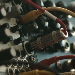
 I have an older server PSU board with 2 replaceable power supplies but the only problem is that the CPU cable is an 8 pin cable and not splittable. The reason for that I think is it has 4 black wires and 2 yellow ones but on of the yellow ones is not next to the other, so it's not connected if I plug it in a 4 pin connector. As I know, the yellow is the 12V, the black is Ground. What I would like to do is to use a cable of a disassembled 230V cable, plug the end next to the target yellow wire and put the other end to the empty pin hole, so it can be connected to the motherboard's connector. But as I'm not an electrician, I would like to ask that is it actually save to use? I won't touch it, of course. The used cable is not a bare copper and it's one of the 3 cables in a 230V wire. Thank you in advance! Don't blame me if it's a bad idea! I took a picture of the cable.
-
is it possible to replace/modify this cable somehow? actually, both of these 4 pin cpu power connectors are burnt/melted. so i am gonna need those both. dont ask how did this happen its a long story but simply seems like m5a97 le r2.0 is not a good choice for 8 thread fx 8320 cpu. cuz the mobo only has 4 pin cpu power entry and stuff.
-
Hello everyone ! Owning an old i5 Asus K56CM with luckily 2 m.2 ports (1 for the wifi and 1 for the useless 24Gb boot SSD) I've decided to upgrade it with a GTX 960 4Gb that I had lying around. To do so, I bought a pci-e -> m.2 Beast Pro adapter from AliExpress but I have a few questions regarding the latter : - what's the 12V input port for ? - I would like to use a PicoPSU to power up the adapter and the 6 and 8 pin required for the GPU, any advice for that ? (I was thinking about getting a psu of at least 150W coupled with a 150-200W power brick 12V but I don't really know how to plug a 6 and 8 pins power adapter to the GPU from a PicoPSU... I only see 6 pins and at best 1 molex adapter on most of them...) Can one molex to 8 pins or even better to 6+8 pins yield enough power for the GPU ? I'm scratching my head to make this smaller factor because I would like to build a little case without using a full ATX PSU to be able to transport that eGPU setup easily in a backpack.