


kkpatel87
-
Posts
543 -
Joined
-
Last visited
Reputation Activity
-

 kkpatel87 got a reaction from Ben17 in NZXT H710 Front panel airflow mod
Very creative, however here are a couple tips to make this look professional:
The cuts look jagged and not-straight. I would recommend more sanding/filing to ensure a straight edge. The corners are probably the worst spot as they draw the eyes to it immediately. Its hard to clean up straight corners but i would have put in some corner rounds. In your case, maybe add some filler to the corners and create a radius. Any time you make a cutout, you should always re-finish the edge. It hides any imperfections and covers any exposed metal. -
 kkpatel87 got a reaction from Jason 57 in NZXT H710 Front panel airflow mod
You can use a dremel but it takes a steady hand. For this kind of application i might use a fine tooth jigsaw or trim router with a endmill.
-
 kkpatel87 got a reaction from sub68 in Spirit of Motion - Scratchbuild Log
Honestly, not my cup of tea but great idea... A few tips:
Keep tolerances in mind when you dimension everything. If you allow for high tolerances, this will turn out much easier for you. Use captive fasteners wherever you can. Model the wiring so you understand how it will look with it. Sometimes wiring isnt taken into account and it looks like crap afterwards. Good luck! Let me know if you need a drawing checker.
-

 kkpatel87 got a reaction from Thony514 in looking for covered led strips
What you are looking for is a diffuser to get rid of the hot spots. You most likely will have to buy the strips and get diffused light bars from a vendor and assemble yourself.
-

-
 kkpatel87 got a reaction from HM-2 in Fittings - Torque, Tape?
First, these are not n00b questions. The unfortunate reality is that most people treat building computers like lazily putting together legos rather than an assembly process. Most Youtubers dont do this either for whatever reasons. Additionally many people will suggest not to as they are confident in their ability to tighten a fitting without process.
Watercooling fittings are considered G1/4 which is a shortened form of 1/4 British Standard Pipe Parallel (BSPP). This is also known as Whitworth threading and is governed by ISO1179. This means the thread type, 1/4"-19, of the fitting is parallel on the male and female side (this is important for later).
Torque ratings for this are majorly dependent on two things, material of fitting and material of internally threaded item (rad, block, etc.). Typically, 30-35 N-m should do it. This is lower than the recommended 50 N-m listed in ISO1179 but i would recommend against that as the materials in computer watercooling are not as strong. However, a good rule of thumb is to tighten 2-3 turns past hand tight.
Unfortunately, no real metric on this one. Tighten the clamp until it bottoms out on the fitting.
This is an O-ring on the base of the fitting that provides the seal. This is typically of flanged, parallel thread pipe fittings. Teflon tape/thread seal is a bad idea in watercooling loops as pieces of that may get into the loop.
-
 kkpatel87 got a reaction from Lurick in 1U Modem/Router Assembly Build Log
Update, I did the coaxial, ethernet and power wiring.
The coaxial cable was terminated first. Just basic 75Ω RG6-Q with two compression type connectors on either end. The cable was quickly tone tested for continuity and installed with the correct torque, 20 in-lbs:
I created a simple power harness for the included power supply. I used M22759/34-14-X for the AC input and same random 20AWG for the DC output. The harness is wrapped in Tesa tape to support the AC in and DC out wires. The continuity was checked with continuity mode on a multimeter:
I had a 50 ft CAT6a shielded cable so i am using that as my CAT6a stock. I used cable matters tool less RJ45 Cat6a connectors. I tested the ethernet connections for continuity:
And lastly, always test your harnesses:
The next update should have the final assembly.
-
.thumb.jpg.d6e03b4dc47b281baa7b97aed6e35663.jpg) kkpatel87 got a reaction from Blue4130 in 1U Modem/Router Assembly Build Log
kkpatel87 got a reaction from Blue4130 in 1U Modem/Router Assembly Build Log
Update, I did the coaxial, ethernet and power wiring.
The coaxial cable was terminated first. Just basic 75Ω RG6-Q with two compression type connectors on either end. The cable was quickly tone tested for continuity and installed with the correct torque, 20 in-lbs:
I created a simple power harness for the included power supply. I used M22759/34-14-X for the AC input and same random 20AWG for the DC output. The harness is wrapped in Tesa tape to support the AC in and DC out wires. The continuity was checked with continuity mode on a multimeter:
I had a 50 ft CAT6a shielded cable so i am using that as my CAT6a stock. I used cable matters tool less RJ45 Cat6a connectors. I tested the ethernet connections for continuity:
And lastly, always test your harnesses:
The next update should have the final assembly.
-
 kkpatel87 got a reaction from kirashi in 1U Modem/Router Assembly Build Log
Update, I did the coaxial, ethernet and power wiring.
The coaxial cable was terminated first. Just basic 75Ω RG6-Q with two compression type connectors on either end. The cable was quickly tone tested for continuity and installed with the correct torque, 20 in-lbs:
I created a simple power harness for the included power supply. I used M22759/34-14-X for the AC input and same random 20AWG for the DC output. The harness is wrapped in Tesa tape to support the AC in and DC out wires. The continuity was checked with continuity mode on a multimeter:
I had a 50 ft CAT6a shielded cable so i am using that as my CAT6a stock. I used cable matters tool less RJ45 Cat6a connectors. I tested the ethernet connections for continuity:
And lastly, always test your harnesses:
The next update should have the final assembly.
-
kkpatel87 got a reaction from kirashi in 1U Modem/Router Assembly Build Log
So this is a bit of a different post...its a network appliance assembly/build log.
I am building a small 6U short depth rack for my living room (Using a Hammond Mfg SDC246U17BK...ill detail that build after i finish this applicance). I selected the ARRIS SB8200 for the modem and the UBNT ERLite-3 for the router. I have not seen a widespread solution to rackmount an ARRIS SB8200 (aside from just using a shelf).
The only thing i would find was a 3D print: https://www.thingiverse.com/thing:4050856
I think the 3d print is a very creative solution but it doesnt solve some of my issues i wanted resolved:
No more than 1U space used. Built in power supply (no external power bricks! (wall worts)). Integration of router Coax disconnect easily reachable with going deep into rack. I went my own way and created a 1U plate assembly housing the ARRIS SB8200 modem, Ubiquiti ERLite-3 router, and power supply. I wanted to ensure i got the most use of 1U with the modem status indicators on the front with all the connections (AC input, 75Ω F bulkhead, and 2x CAT6A keystone jacks) on the back. I selected the MeanWell LRS-50-12 for the power supply for both the modem and router.
NOTE: In the future, i might take both PCBs out of the modem and router and put it into a custom 1U short depth chassis but this is an interim solution.
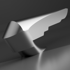
Here is a screenshot of the 3d assembly i created with 2 parts, a main plate and a front plate:
Both parts are made from 0.063" 5052-H32 aluminum alloy per SAE AMS QQ-A-250/8. The main plate has two flanges formed via bending. The front plate will attach to the main plate via rivets.
Here are the router, modem, and power supply laid out on the plate, pre-form:
Here is the sheet metal assembly temporarily assembled:
I potted #10-32 inserts on the bottom of the modem and router. This way all the units are fastened from the bottom.
Here is what i have planned next:
Temporarily install modem, router, psu, and connectors Create wiring harnesses (Coax, 2x ethernet, and power) I haven't detailed everything so please feel free to ask questions and i will do my best to answer!
-
kkpatel87 got a reaction from sub68 in Amd x2 250 storage server
I would upgrade to 8GB, even at a basic level for FreeNas. You can use XigmaNAS as well or honestly any linux distro would work.
-
 kkpatel87 got a reaction from Electronics Wizardy in Help planning a file server
For something like this, i would suggest something from Dell EMC or HPE. Unless you are very experienced in enterprise or critical environments, i would suggest you go the pre-built route.
What does the network map look like? Will all the users be accessing the server locally or remotely?
This is a system architecture problem so i would recommend approaching it from that viewpoint.
-
kkpatel87 got a reaction from Lurick in 1U Modem/Router Assembly Build Log
So this is a bit of a different post...its a network appliance assembly/build log.
I am building a small 6U short depth rack for my living room (Using a Hammond Mfg SDC246U17BK...ill detail that build after i finish this applicance). I selected the ARRIS SB8200 for the modem and the UBNT ERLite-3 for the router. I have not seen a widespread solution to rackmount an ARRIS SB8200 (aside from just using a shelf).
The only thing i would find was a 3D print: https://www.thingiverse.com/thing:4050856
I think the 3d print is a very creative solution but it doesnt solve some of my issues i wanted resolved:
No more than 1U space used. Built in power supply (no external power bricks! (wall worts)). Integration of router Coax disconnect easily reachable with going deep into rack. I went my own way and created a 1U plate assembly housing the ARRIS SB8200 modem, Ubiquiti ERLite-3 router, and power supply. I wanted to ensure i got the most use of 1U with the modem status indicators on the front with all the connections (AC input, 75Ω F bulkhead, and 2x CAT6A keystone jacks) on the back. I selected the MeanWell LRS-50-12 for the power supply for both the modem and router.
NOTE: In the future, i might take both PCBs out of the modem and router and put it into a custom 1U short depth chassis but this is an interim solution.
Here is a screenshot of the 3d assembly i created with 2 parts, a main plate and a front plate:
Both parts are made from 0.063" 5052-H32 aluminum alloy per SAE AMS QQ-A-250/8. The main plate has two flanges formed via bending. The front plate will attach to the main plate via rivets.
Here are the router, modem, and power supply laid out on the plate, pre-form:
Here is the sheet metal assembly temporarily assembled:
I potted #10-32 inserts on the bottom of the modem and router. This way all the units are fastened from the bottom.
Here is what i have planned next:
Temporarily install modem, router, psu, and connectors Create wiring harnesses (Coax, 2x ethernet, and power) I haven't detailed everything so please feel free to ask questions and i will do my best to answer!
-
 kkpatel87 got a reaction from mayhem_modz in CYBERPUNK 2077 YAIBA KUSANAGI scratch build SPONSORED *HWLEGEND MODDING TEAM* CMWS2020
This looks pretty cool! Cant wait for updates.
Would you consider using solid rivets over blind rivets? I think it would look much better from a aesthetic and workmanship perspective.
-
 kkpatel87 got a reaction from Tookey423 in NZXT H710 Front panel airflow mod
Very creative, however here are a couple tips to make this look professional:
The cuts look jagged and not-straight. I would recommend more sanding/filing to ensure a straight edge. The corners are probably the worst spot as they draw the eyes to it immediately. Its hard to clean up straight corners but i would have put in some corner rounds. In your case, maybe add some filler to the corners and create a radius. Any time you make a cutout, you should always re-finish the edge. It hides any imperfections and covers any exposed metal. -
.png "Funny")
 kkpatel87 got a reaction from Nena Trinity in Dust cleaned rig... OwO
Wire routing on both systems could use some help.
What are your plans for these machines?
-
kkpatel87 got a reaction from SHADFAN in PC BUILT IN DESK (not completed yet)
I understand you are only 16 but i think it would behoove you to make some adjustments:
That base looks like foam glued together. It does not looked like its mean to bear any load. I would recommend replacing that with wood. Create a fan bracket instead of gluing a fan to the inside. That will not end well. That wiring and components installation in the back is nonsensical and needs to be fixed. Why are the components just attached randomly? Why don't you make a small plate assembly? Also, a breadboard is not meant to be used in a final application, only for prototyping. Why don't you create a wire harness and make it look more professional? Please note everything said here is to help you. Right now this is not going to shape up to be a decent build. If you don't care about the above, that's your prerogative but if you need help there are plenty of people here that would be willing to do so.
-
kkpatel87 got a reaction from sub68 in a sleeper from a dell vostro 260 case
That paint and masking job does not look very good. Are you going to touch that up or something?
-
 kkpatel87 got a reaction from cmcman21 in is there a market for 2000$ pcs made by a person and not a company?
Well, what is your value proposition? What do you offer that no one else does? There are lots of boutique builders and custom modders that have cornered this market.
From what i understand profit margins are pretty small in this space. There is definitely a market but you have to have a well thought out plan before entering it.
-
 kkpatel87 got a reaction from doommood in I need a server to share photos with my friends.
You could create an owncloud or use a commercial NAS like Synology and their own version of cloud sharing.
-
 kkpatel87 got a reaction from MaximumBubbleMods in Spirit of Motion - Scratchbuild Log
The corners dont look square...is that intentional?
-
 kkpatel87 got a reaction from Heeelion in First Build H510i Build RTX 2070 Super GAMING X - Ryzen 3700x
I don't believe individually sleeved wire is a step up. The intent of multicolor wire is to allow easy and effective identification of signal types. The only reason to individual sleeve cable is this current subjective fad of appearance. To me, form does not supersede function and that's why it is irritating to me when everyone says "ketchup and mustard" cables. That being said, i am definitely in the minority when it comes to that opinion haha.
-
kkpatel87 got a reaction from Heeelion in First Build H510i Build RTX 2070 Super GAMING X - Ryzen 3700x
Here are the notes i have:
GPU power input is awful. You need to either change the power cable or create your own harness. Not huge fan of that bracket since it is another cantilever beam. The silverstone bracket is hidden but very well built. Main Mobo power looks so odd. I would use a adapter to change the angle. I am thoroughly terrified to see what the basement and side panel look like Yeah....plz fix lol
Nah...regardless of the orientation, as long as there is no sag and the power cables are routed nicely, it doesnt matter
Yeah but taking time to do it correctly and neatly shows care and attention to detail to me. Also who case if your friends would notice? But if you are proud of it the way it is, then its fine.
-


.thumb.jpg.d6e03b4dc47b281baa7b97aed6e35663.jpg)


